ZYNQ MPSOC-Based Ship Data Acquisition Instrument Design (Part 3): Vibration, Flow, Power Consumption, EMC, and Reliability Testing
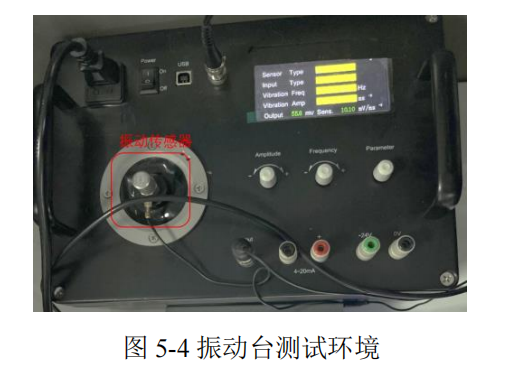
5.3.1 Vibration Signal Acquisition Channel Performance Testing
To ensure the vibration signal acquisition channel can filter out high-frequency noise, an anti-aliasing low-pass filter circuit was designed in this paper. Simulation tests were performed using Multisim software. The simulation schematic is shown in Figure 5-2 a), and the amplitude-frequency characteristic curve is shown in Figure 5-2 b). When the gain is -3dB, the cutoff frequency is approximately 11kHz, which meets the design specifications.
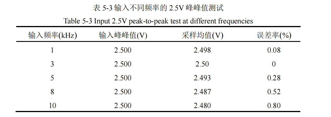
Next, to verify the AD7768's acquisition performance for different analog vibration signals at a 128 kHz sampling rate, a signal generator was first used to output 2.5 V signals of various frequencies. Each frequency signal was tested 20 times, and the sampled voltage was compared with the actual 2.5 V. The summarized test data is shown in Table 5-3.
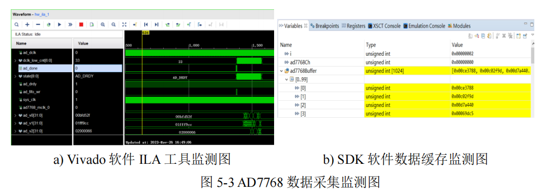
AD7768 vibration signal acquisition monitoring is shown in Figure 5-3. Online monitoring was performed using the Logic Analyzer (ILA) probes integrated into Vivado software (as shown in Figure 5-3 a)), and the data in the AD7768 driver cache was monitored using SDK software (as shown in Figure 5-3 b)).
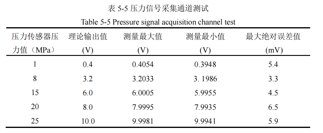
5.3.3 Pressure, Liquid Level, and Flow Signal Acquisition Channel Performance Testing
Due to the lack of real ship environment test conditions, the test plan was based on the sensor manufacturer's calibration curve values. To ensure data reliability, a high-precision programmable power supply (accuracy ±0.01% FS) was used as the standard input source. Data was monitored in real-time online via SDK software. Specifically, the input voltage was tested for the pressure signal acquisition channel, and the input current was tested for the liquid level and flow signal acquisition channels. Each test was repeated 20 times, and extreme values were recorded to determine the maximum absolute error. The power supply equipment connection is shown in Figure 5-6.
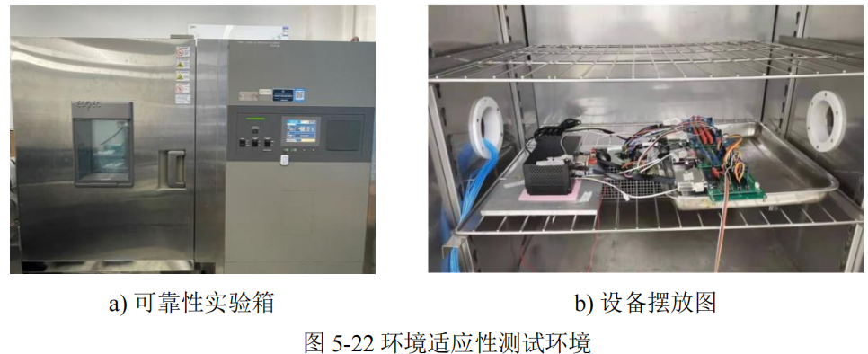
5.7 Cabin Environment Adaptability Testing
To ensure the reliability and durability of the multi-parameter data acquisition and recording device for ship cabins in harsh marine environments, and in accordance with Classification Society GD28-2023 "Guidelines for Reliability Verification of Marine Equipment and Systems" [64], comprehensive environmental adaptability tests were conducted on the device in a reliability test chamber. The tests included temperature and humidity adaptability testing, salt spray testing, vibration testing, and electromagnetic compatibility testing. The test environment is shown in Figure 5-22.