TI AM5728 OMAP Platform BSP Learning Notes - LCD Driver (1)
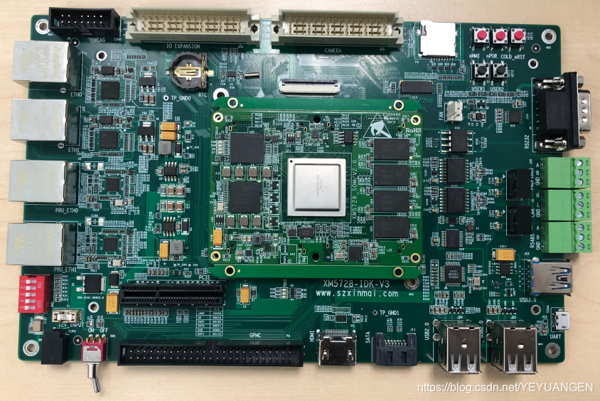
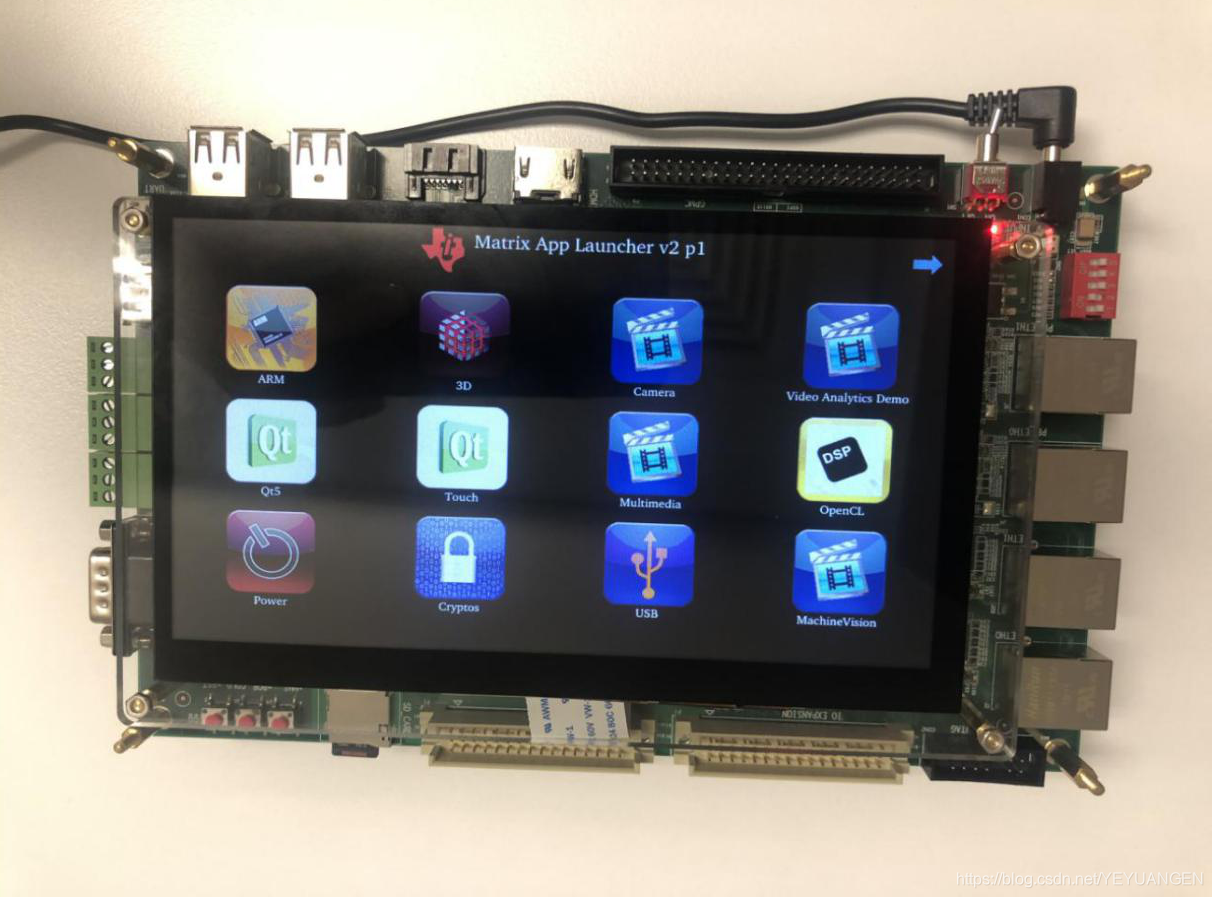
Copyright Notice: This article is an original work by the blogger. Please cite the source when reprinting. Commercial use is not permitted without the blogger's permission. If you have any questions, feel free to point them out. https://blog.csdn.net/hsg\_\_tg2/article/details/86703168 The development board referenced in this article is the Sienovo XM5728-IDK-V3 series development board.
The LCD driver is part of the Display Subsystem (DSS). DSS is an abbreviation for Display Subsystem. In the kernel, DSS can be implemented using either framebuffer or DRM, selectable through different configurations. This article will cover the basic knowledge of DSS, and later we will study the LCD driver code for porting.
It's important to note that the display system is a module independent of the GPU. We use the GPU for rendering and compositing, typically targeting image buffers. The display's primary purpose is to display, although it also supports simple graphics transformations and compositing. The TI OMAP platform has separate GPU acceleration modules for image operations.
- OMAP DSS Framework We know that the purpose of a driver is to control and drive hardware devices. DSS is divided into two parts in terms of hardware:
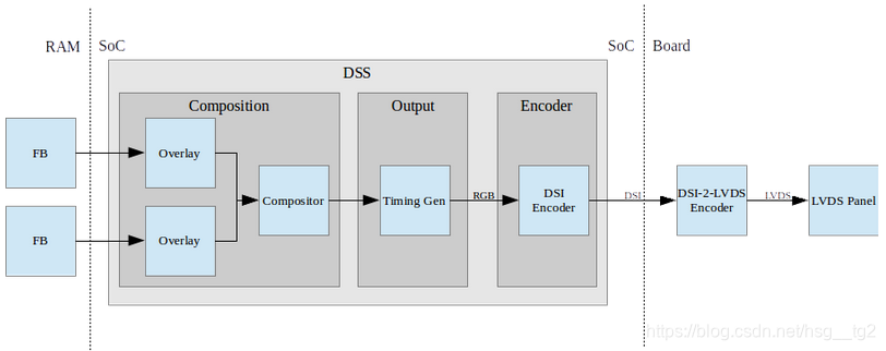
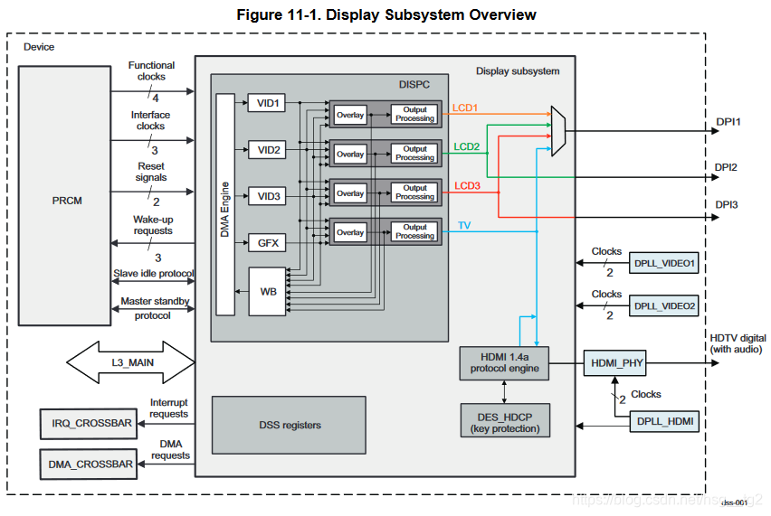
DISPC, the display controller, primarily handles overlays, which means combining multiple graphics buffers as input into a single output. For example, interfaces from two different applications, status bar interfaces, mouse pointers, etc., can all be inputs. At the same time, ICs from different manufacturers may add image processing capabilities to this module, such as color transformation, gamma correction, and image rotation. This depends on how it fetches data from RAM and can process graphics buffers (e.g., deformation, rotation). TI's display subsystem is similar, though different versions may vary slightly; refer to the linked resources for details. Encoders convert the controller's data into output signals, such as HDMI, MIPI DPI, etc. At the board level, they can directly connect to LCDs that support the corresponding interfaces (or external encoders, such as DPI-DVI converters, to support different display devices).
1.1 DISPC
Overlays fetch image data from SRAM for transformations, scaling, etc. The OMAP platform includes two types of overlay hardware: GFX and VIDEO. GFX does not support scaling or YUV formats and is typically used for UI display rather than video.
The Overlay Manager's main function is to composite and generate timing. As mentioned earlier, compositing means combining data from multiple overlays into a single buffer. This module can also perform simple graphic transformations. Furthermore, it can generate timing signals such as pixel clock, hsync, vsync, data enable, and RGB data according to the requirements of the encoder or panel. With these timing signals, OMAP chips can support LCDs without GRAM by directly refreshing image buffers through timing control.
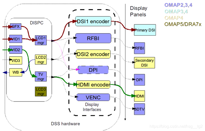
As shown in the figure above, the functionalities of DISPC vary across different models.
1.2 Encoder The encoder, also known as an interface, converts the composited image data into a standard stream format and then sends it to the corresponding peripheral for display. As shown in the figure above, OMAP supports standards such as MIPI DPI, HDMI, MIPI DSI, and MIPI DBI/RFBI.
The DPI (Display Pixel Interface) is also known as the RGB interface. The host directly writes data to the screen for display, requiring operations under the host's own timing. The DBI (Display Bus Interface) does not require the host to have timing control. It directly writes control and RGB data via data lines into the LCM's GRAM, and the panel's driver IC then retrieves data from GRAM to refresh the screen. MIPI DSI differs from the two parallel interfaces mentioned above; it is a serial standard interface supporting both video and command modes. Later, when studying the AM5728 platform, you will find that it typically uses the DPI interface.
- Introduction to AM5728 DSS and Interfaces AM5728 is a type of OMAP, and as shown below, its structure is largely similar:
3 video pipelines, 1 GFX pipeline, 1 write-back pipeline; 3 LCD outputs (DPI), 1 TV output (can output to HDMI or DPI).
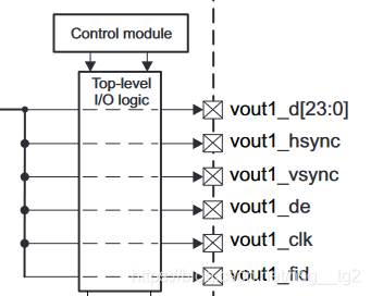
 We mainly focus on the DPI interface, illustrated below. These signals are directly connected to the LCD, refreshing the input onto the LCD display.
d[23:0] are 24 data lines, supporting up to 24-bit color depth, chosen according to the specific panel. Information on how to connect them is provided in the reference documentation. clk refers to the pixel clock; hsync and vsync are horizontal and vertical synchronization signals; de is the data enable signal; fid refers to the field identifier setting.
 3. MIPI DPI Interface Introduction
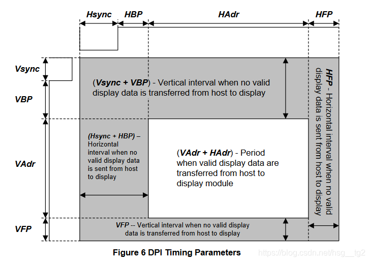
The DPI interface is also known as the RGB interface, where the host directly writes RGB data synchronously to the LCD for display. The host operates using the timing and data lines described in the previous section. As shown in the figure below, the white area is the screen area, synchronized horizontally by hsync and vertically by vsync. The white area in the middle is the LCD display area. These parameters need to be properly configured in the LCD driver.
3. MIPI DPI Interface Introduction
The DPI interface is also known as the RGB interface, where the host directly writes RGB data synchronously to the LCD for display. The host operates using the timing and data lines described in the previous section. As shown in the figure below, the white area is the screen area, synchronized horizontally by hsync and vertically by vsync. The white area in the middle is the LCD display area. These parameters need to be properly configured in the LCD driver.
Reference Documents:
http://processors.wiki.ti.com/index.php/Linux\_Core\_DSS\_User%27s\_Guide
https://blog.csdn.net/longxiaowu/article/details/24249971
AM572x Sitara ™ Processors Silicon Revision 2.0, 1.1 Technical Reference Manual
MIPI Alliance Standard for Display Pixel Interface
Author: Buddhist Code Reader Source: CSDN Original: https://blog.csdn.net/hsg\_\_tg2/article/details/86703168 Copyright Notice: This article is an original work by the blogger. Please include the blog post link when reprinting!