TI AM5728 LCD Touchscreen Driver Porting and DTS Configuration
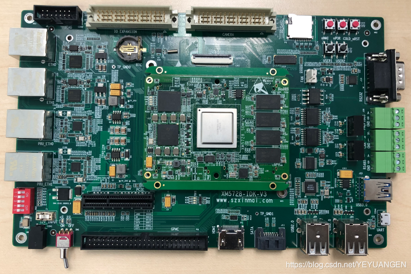
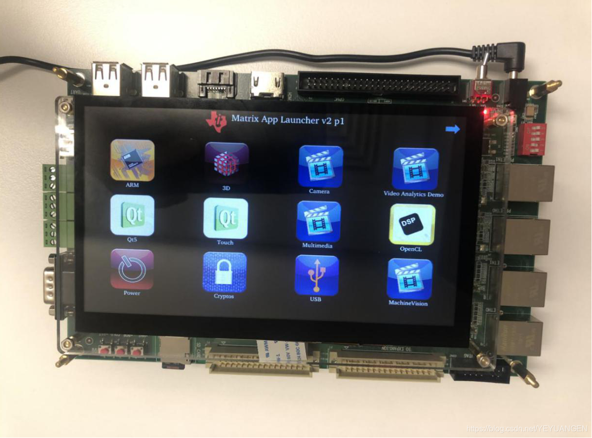
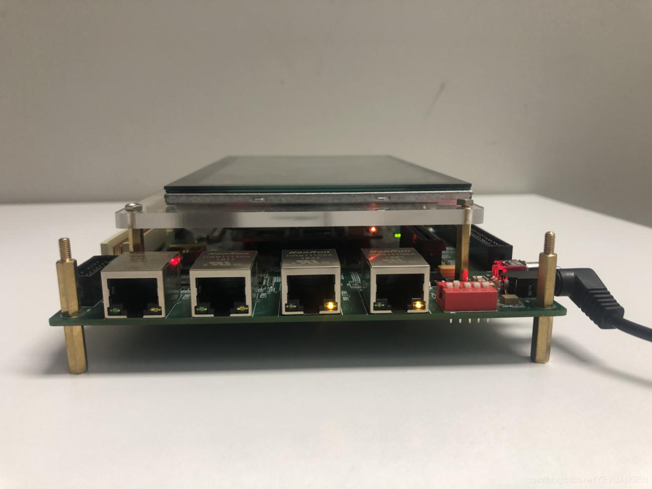
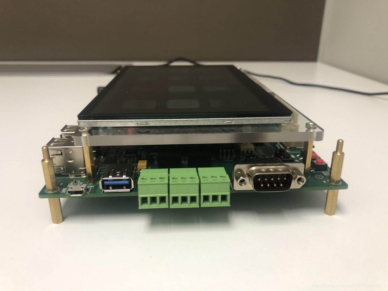
Adding an LCD screen to the Sienovo XM5728-IDK-V3 development board. The result after successful integration:

References: Porting LCD on AM335x using DTS (Part 1) https://blog.csdn.net/xiaojiezuo123/article/details/49890733
For driver source code, add WeChat: 13670212541, technical discussions are welcome.
Debugging Experience/Notes:
Development Environment: Using Sienovo AM5728 core board, the board is self-developed by the company, LCD models are: AT080TN64, AT070TN94
Issues encountered:
1. No /dev/fb0 device node was created.
2. LCD text display order was reversed.
3. LCD colors were incorrect.
The LCD-related configuration in the device tree is as follows:
aliases {
    display1 = &lcd;
    rtc0 = &tps659038_rtc;
    rtc1 = &isl1208_rtc;
};

lcd_bl: backlight {
    compatible = "pwm-backlight";
    pwms = <&ecap0 0 50000 0>;
    brightness-levels = <0 51 53 56 62 75 101 152 255>;
    default-brightness-level = <8>;
};

lcd: display {
    compatible = "osddisplays,osd070t1718-19ts", "panel-dpi";
    enable-gpios = <&gpio3 30 GPIO_ACTIVE_HIGH>;
    backlight = <&lcd_bl>;
    label = "lcd";
    panel-timing {
        clock-frequency = <33300000>;
        hactive = <800>;
        vactive = <480>;
        hfront-porch = <210>;
        hback-porch = <46>;
        hsync-len = <20>;
        vfront-porch = <22>;
        vback-porch = <23>;
        vsync-len = <10>;
        hsync-active = <1>;
        vsync-active = <1>;
        de-active = <0>;
        pixelclk-active = <0>;
    };
    port {
        lcd_in: endpoint {
            remote-endpoint = <&dpi_out>;
        };
    };
};

&dss {
    status = "okay";
    vdda_video-supply = <&ldoln_reg>;
    ports {
        #address-cells = <1>;
        #size-cells = <0>;
        port {
            reg = <1>;
            dpi_out: endpoint {
                data-lines = <24>;
                remote-endpoint = <&lcd_in>;
            };
        };
    };
};
Analyzing the causes of the issues:
-
In the kernel print messages, repeatedly appeared: Linked as a consumer to regulator.20 Dropping the link to regulator.20
-
Pinmux settings for the LCD were incorrect.
-
The driver corresponding to
compatible = "panel-dpi"in the device driver had issues. -
Setting
.bus_format = MEDIA_BUS_FMT_RGB888_1X24in the driver, which can change the RGB data format and output RGB data in different formats. -
Hardware issues with the LCD driver board.
-
Issues with the LCD output timing.
Problem-solving process:
-
regulator.20is located under the/sys/class/regulator/device node, the voltage is 1.8V, and multimeter measurements also showed it to be normal. -
Even after configuring pinmux in the device tree, no node was generated.
-
Upon checking the driver directory corresponding to
panel-dpi, it was found that this driver was not compiled, so there might be an issue with device matching. -
Changing the format to BGR, GRB, etc., did not change the display effect.
-
Measured whether the pins on the LCD driver board and the core board were connected.
-
Used an oscilloscope to check if the LCD output timing was incorrect.
Issues resolved:
1. By changing compatible to compatible = "osddisplays,osd070t1718-19ts", "panel-dpi";, the /dev/fb0 device node can be generated.
2. LCD colors were incorrect; measuring the voltage with a multimeter, it was found that the IO voltage of the LCD driver board was too high. The hardware team just needed to add a resistor to the driver board.