Design of an Elderly Care Robot Vision System for Dangerous Behavior Monitoring Based on the Jetson Platform
I. Introduction
With the escalating aging population in China, home-based elder care has become an important mode of elderly support. However, elderly individuals living at home face numerous potential risks from dangerous behaviors. Therefore, researching how to effectively monitor dangerous behaviors in the elderly holds significant practical importance and social value. The design and research of an elderly care robot system aim to leverage advanced vision algorithms and robotic technology to provide real-time and accurate dangerous behavior detection, timely alarm functions, video surveillance, and remote control capabilities, thereby ensuring the safety and health of the elderly and improving the quality and effectiveness of home-based elder care.
II. Elderly Care Robot System Design
2.1 Overall Design of the Elderly Care Robot System
This system consists of three parts: the elderly care robot, the cloud server, and the client software. The most complex part is the elderly care robot, whose hardware includes a vision processor, motion controller, chassis, gimbal, lidar, gyroscope, Bluetooth, motor driver board, and Wi-Fi. The connections between these controllers and peripherals are shown in Figure 2-1. UART1 and CAN interfaces are designed for future expansion of peripherals.
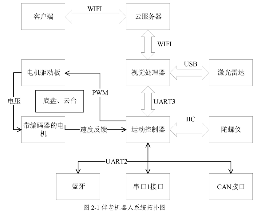
The robot adopts a dual-processor architecture: the vision processor has high computing power, capable of running complex vision algorithms, but its interrupt response is slow due to running a time-sharing operating system; the motion controller, on the other hand, runs a real-time operating system, specifically designed to compensate for the vision processor's shortcomings in interrupt response. This dual-controller design ensures both the powerful computing capability required for vision algorithms and the fast response needed for peripheral interrupt requests, achieving an organic combination of high computing power and rapid response. The two processors communicate via a serial port.
The three components of the system—the robot, cloud server, and client—are all connected via Wi-Fi. The cloud server has a public IP address. The robot sends camera data and alarm information to the server, which then forwards it to the client software. This architecture ensures stable network connectivity for the robot, while allowing the client to remotely control the robot and view its camera data in real-time.
The robot's external lidar and gyroscope are used for 3D modeling of the indoor environment and establishing a global coordinate system. The Bluetooth module supports user control of the robot's movement via a Bluetooth connection.
The robot's gimbal is designed to allow the camera to rotate 360 degrees, enabling monitoring of the elderly without blind spots. Both the gimbal and the chassis motors are controlled by PWM waves, and each motor is equipped with an encoder to achieve PID closed-loop control, precisely outputting speed and calculating movement distance and direction, thereby determining the robot's pose in the aforementioned global coordinate system.
The general workflow of the system is as follows:
First, the three parts of the system establish communication connections: the robot establishes TCP and UDP communication with the cloud server via Wi-Fi, and the cloud server also establishes TCP and UDP communication with the client software via Wi-Fi. The TCP protocol is used to transmit robot information (such as robot ID, UDP port number returned by the cloud server, etc.) and motion control commands from the client; the UDP protocol is used to transmit video stream data. Communication between the vision processor and the motion controller is established via a serial port.
The vision processor first configures the camera and starts three threads (all these threads are located in the vision detection node in the ROS node graph in Section 2.2.3): the first is the video surveillance thread, responsible for sending camera data to the cloud server; the second is the fall detection thread, which runs the fall detection algorithm after the camera is enabled. Once a fall is detected, it notifies the third thread—the alarm thread—via a fall identifier. Simultaneously, the vision system publishes a navigation topic to the navigation node, guiding the robot to move to the elder's side for further inspection; the alarm thread then sends the fall event to the cloud server via Wi-Fi.
Upon receiving the alarm information uploaded by the robot, the cloud server forwards the fall event to the client; concurrently, it can also forward control commands from the client to the robot.
The client can remotely view the robot's camera data, remotely control the robot via the cloud server, and receive alarm information promptly when a fall occurs, generating an alarm log. The alarm log includes the fall time and the path to the fall image file.
In summary, the overall system structure of the elderly care robot, from a hardware and communication perspective, can achieve functions such as automatic obstacle avoidance, running vision-based fall detection algorithms, remote motion control, remote video surveillance, and IoT capabilities. The subsequent sections of this chapter will elaborate on the design of the elderly care robot's vision and motion control systems and their collaborative operation.
2.2 Elderly Care Robot Motion Control System
2.2.1 Hardware Components
(1) Omnidirectional Wheel Chassis
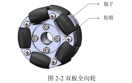
The elderly care robot uses an omnidirectional wheel chassis to meet the research objective of all-directional robot movement. The omnidirectional wheels consist of double-layer passive rollers, with the two rollers offset from each other. This design aims to avoid the dead zone problem present in single-disk omnidirectional wheels.
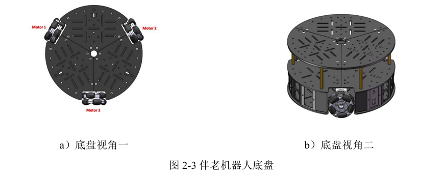
In the three-wheel omnidirectional mobile chassis, three double-row omnidirectional wheels are distributed at 120° on the chassis frame. Each wheel has an independent DC geared motor, and each DC geared motor is equipped with an encoder at the rear to measure the motor's rotational speed, which in turn gives the wheel's rotational speed. By synthesizing these speeds, the final motion speed and direction are obtained.
(2) Two-Degree-of-Freedom Gimbal
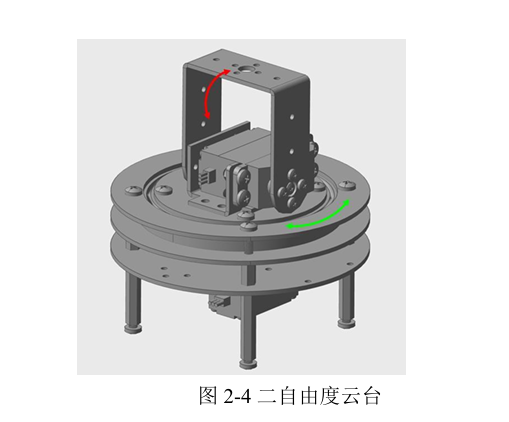
The main function of the gimbal is to support and fix the camera, enabling two degrees of freedom of movement. These two degrees of freedom are yaw rotation and pitch rotation, used to achieve 360-degree rotation and tilting of the camera. Through the cooperation of these two joints, the robot's head can move flexibly, achieving full-range scanning of the surrounding area.
(3) Lidar
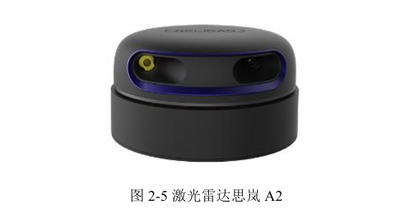
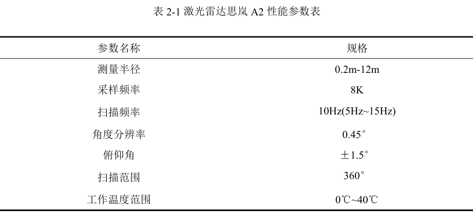
For a robot to move freely in a home environment, obstacle avoidance, navigation, and map building are essential. Therefore, a sensor capable of perceiving the surrounding environment is needed for the robot, and lidar is a commonly used sensor that can collect high-precision point cloud data, which is then used for environment modeling and robot localization. In the robot system designed in this paper, the RPLIDAR A2 developed by Slamtec is used. In this system, the main functions of the lidar are: first, to model the home environment and establish a global coordinate system; second, to scan for obstacles encountered during the robot's movement for obstacle avoidance; and third, to localize the robot within the global coordinate system.
(4) Motion Controller
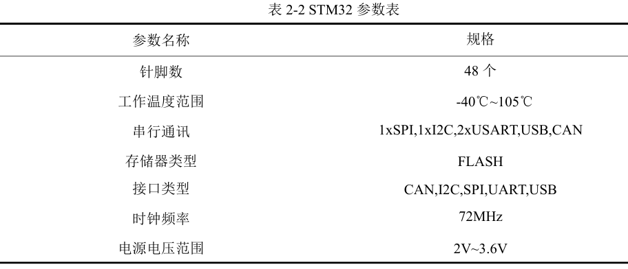
The robot's motion controller is designed on a PCB, integrating three motor interfaces with encoders, an STM32F407 microcontroller, a Bluetooth chip, an IMU gyroscope sensor, a CP2102 level-shifting serial communication interface, and a gimbal interface. The STM32 controller's role is to control chassis movement, collect odometry information, battery information, and IMU information, and communicate with the vision processor via a serial port to receive motion commands from the vision processor, configuring the vision processor to complete the task of moving to the elder's side after a fall.
2.2.2 Design of Communication Interface between Robot Motion and Vision Systems
The purpose of designing communication between the vision processor and the STM32 motion controller is twofold: first, to ensure that the vision processor can obtain the robot's position information in the global coordinate system in real-time; second, to transmit motion commands to the motion controller to assist the vision system in completing various tasks. Both systems use serial communication, with the STM32 controller occupying UART3 at a baud rate of 115200. The communication process includes: the STM32 controller sending collected odometry information, battery voltage information, and other data to the vision processor; the vision system publishing navigation topics to the motion control system, which then parses the topics and sends data frames to the STM32 via the serial port.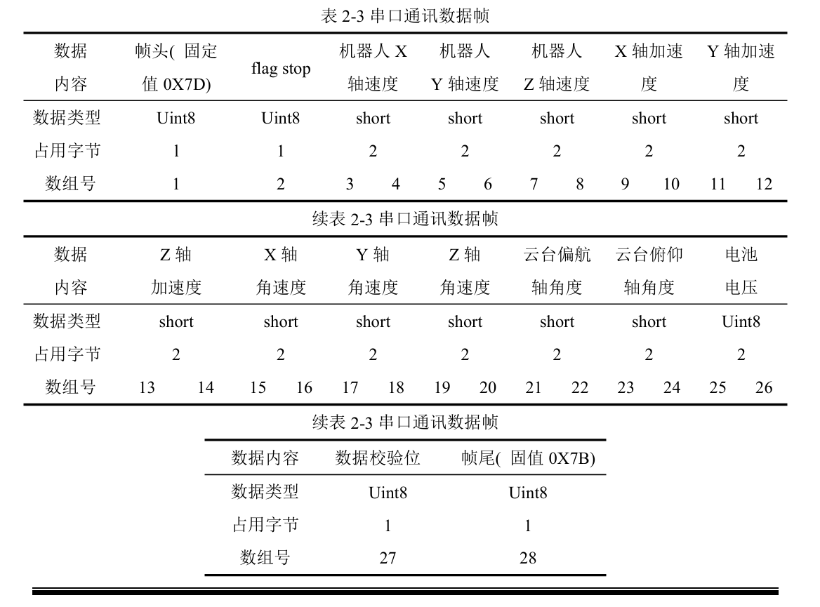
In this paper, the data sent from the STM32 to the vision processor is packaged into a 28-bit array, which is considered a data frame. The first and last bits of the data frame are fixed values (frame header and frame tail), the second bit is the robot enable control bit, which is open by default, meaning the robot is allowed to perform actions. Bits 3 to 20 contain the speed and acceleration information for the three axes of the robot chassis. Bits 21 to 24 represent the two angles of the gimbal. Bits 25 and 26 contain battery voltage information. The 27th bit is the data checksum bit, using CRC (Cyclic Redundancy Check) in this paper. The software implementation of the above communication involves creating a date_task task on the FreeRTOS real-time operating system running on the STM32 motion controller. Within this task, the aforementioned data frame is sent to the vision processor via UART3 at a frequency of 20 Hz, allowing the vision processor to constantly know various information about the robot hardware.
2.2.3 Interaction between Robot Motion and Vision Systems
For the robot to move safely and stably in a home environment, the following requirements must be met:
(1) Map the home environment and establish a global coordinate system;
(2) The robot must always know its current pose in the global coordinate system;
(3) Possess automatic navigation and obstacle avoidance capabilities.
This paper has already completed the selection of the lidar sensor in Section 2.2.1. For lidar development, this paper uses the ROS (Robot Operating System) platform, which has many open-source robot algorithms. For example, the aforementioned map building can use the gmapping algorithm, robot localization can use the amcl package, and navigation can use the move_base package. As long as the robot's target position and orientation on the map are determined, the robot can reach that target position on the map according to the optimal path. This greatly reduces the development of many non-critical programs, and the ROS platform also facilitates code modification and debugging.
Based on this, this paper adopts the ROS system to implement the robot's motion functions. Since the focus of this paper is on the vision system, the interaction between the vision system and the motion control system will be emphasized, and detailed descriptions of forward and inverse kinematics in the motion system will not be provided.
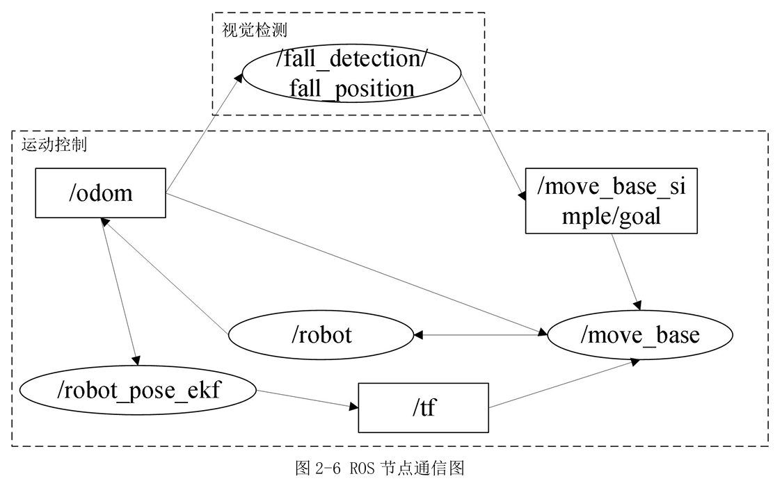
This section focuses on how the vision and motion systems cooperate. According to the business logic, when the vision detection node detects an elder's fall, the robot needs to move to the elder's side for inspection. Therefore, the vision detection node needs to know the elder's fall position and publish this information to the navigation node.
In the ROS system, data transfer between different nodes can be achieved by subscribing to and publishing topics. In Figure 2-6, the /fall_detection/fall_position node obtains the robot's current pose by subscribing to the /odom topic. When a fall occurs, it calculates the elder's fall position (x, y coordinates) through coordinate transformation, and then publishes this fall position as the navigation target to the /move_base_simple/goal topic for the /move_base node. Once the /move_base navigation node receives this, the robot will move to the elder's side according to the navigation algorithm.
2.3 Elderly Care Robot Vision System
2.3.1 Hardware Components
(1) Depth Camera
The goal of this paper is to perform fall detection based on vision technology, and its technical approach utilizes 3D vision for algorithm design. Therefore, the elderly care robot vision system in this paper needs to select a depth camera that meets the following aspects:
① Suitable for indoor environments and stable operation.
② Easy to develop, with a mature SDK available.
③ Rich interfaces, with data and power cables conforming to conventional hardware interfaces, compatible with the vision processor.
④ High image quality, capable of accurately and quickly acquiring depth information.
(2) Vision Processor
One of the goals of this paper is to run vision-based fall detection algorithms on the robot, so a suitable vision processor needs to be selected that meets the following requirements:
① Powerful computing performance, capable of quickly completing image processing and model execution tasks;
② Moderate size, able to adapt to the space constraints on the robot without affecting its movement and balance;
③ Rich interfaces and expansion capabilities, compatible with other peripherals such as STM32 and KinectDK;
④ Wi-Fi module support, capable of connecting to the network and sending/receiving data to/from the cloud server.
2.3.2 Selection of Robot Vision Processor
Raspberry Pi 4B and Jetson Nano are both mainstream robot vision processors. One is a classic single-board computer, suitable for low-power, cost-sensitive applications. The other, Jetson Nano, is an AI development board launched by NVIDIA, possessing GPU acceleration capabilities.
After comparison, it was found that Jetson Nano has a higher topic publishing frequency when running face recognition, image transmission, and color image tracking programs, while Raspberry Pi is faster when tracking color blocks in depth maps. Overall, Jetson Nano performs better. In summary, Raspberry Pi has stronger CPU performance, while Jetson Nano has advantages in image processing and memory. Since the goal of this paper is to run vision programs on the processor, Jetson Nano will be selected as the vision processor.
2.3.3 Robot Vision System Algorithms
After comparing traditional vision-based fall detection techniques, the method utilizing skeleton keypoints shows clear advantages in detecting dangerous behaviors like falls. By identifying skeleton keypoints of key human body parts, human posture and motion information can be captured more accurately, thereby achieving efficient detection and analysis of fall behaviors. Compared to traditional methods, skeleton keypoint technology is not affected by background interference, possessing stronger anti-interference capabilities. At the same time, because keypoint information is more refined and accurate, it can provide more reliable fall warnings and risk assessments.
Skeleton keypoint recognition is an important task in the field of computer vision, aiming to detect and locate human joints from images or videos. Current skeleton keypoint recognition methods are mainly divided into two categories: bottom-up and top-down.
Top-down method: The top-down method first performs human detection on the entire image, identifying all possible human regions, and then performs keypoint detection and localization for each detected human region separately. This method typically includes the following two steps:
Human Detection: In this step, pre-trained object detection models (such as Faster R-CNN, SSD, or YOLO) are typically used to detect humans in the image. The detection results include multiple bounding boxes, each corresponding to a human instance.
Keypoint Detection: For each detected human instance, a pre-trained keypoint detection model (such as OpenPose, Hourglass, or CPM) is used to detect and localize its keypoints. Finally, the complete human pose is constructed by connecting the keypoints.
Bottom-up method: The bottom-up method directly detects keypoints on the entire image and then groups the detected keypoints according to specific rules to form the poses of different humans. This method mainly includes the following two steps:
Keypoint Detection: A pre-trained keypoint detection model (such as OpenPose, Hourglass, HigherHRNet, or CPM) is used to detect keypoints on the entire image. Unlike the top-down method, the bottom-up method does not require human detection.
Keypoint Grouping: The detected keypoints are grouped according to certain rules (such as distance, direction, color, etc.) to form the poses of different humans. Grouping methods typically include heuristic search, graph partitioning, or the use of graph neural networks.
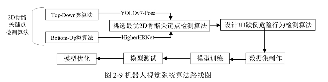
The functional positioning of the elderly care robot's vision system in this paper is primarily video surveillance and fall detection, with the fall detection algorithm being the key technology. The goal of the vision-based fall detection algorithm in this paper is to design a 3D vision-based fall detection algorithm based on 2D skeleton keypoint detection algorithms and coordinate transformation. First, two mainstream 2D skeleton keypoint detection algorithms are compared, and the one with the best experimental results is selected as the basis for the 3D vision-based fall detection algorithm. Building upon this, coordinate transformation is performed, a dataset for the 3D vision-based fall detection algorithm is created, and then the model is trained, tested, and optimized.