CPLD+MCU-based 3U Chassis Digital Input Acquisition Board (DI) for Standard DC110V Digital Switch Signal Acquisition and Processing
This article introduces Sienovo's 3U-form-factor Digital Input (DI) acquisition board, a purpose-built embedded hardware module for reliably capturing and processing standard DC 110 V digital switch signals in industrial environments. If you are evaluating board-level I/O solutions for railway, power-grid SCADA, or substation automation systems—where 110 V DC logic levels are the norm—this design walkthrough covers the key architectural decisions, component choices, and electrical specifications you need.
Why DC 110 V Switch Signals?
Industrial control systems inherited the 110 V DC signaling standard from decades of railway and utility practice. Unlike the 24 V DC common in factory automation, 110 V DC provides inherent noise immunity over long cable runs and allows legacy relay circuits to interoperate with modern digital I/O cards without a separate voltage converter at the field end. Any DI acquisition board targeting this domain must handle the high-side voltage safely while ultimately converting the signal to logic levels digestible by a microcontroller or FPGA.
Board Overview
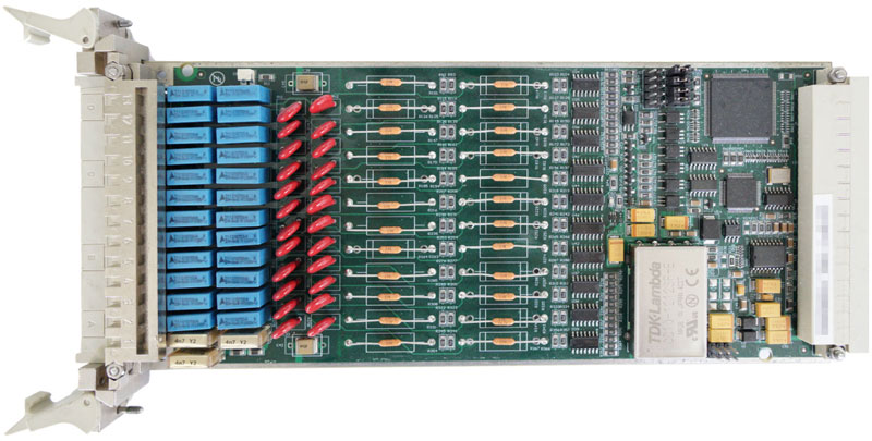
The DI board is a standard 3U card (220 mm × 100 mm, 1.6 mm PCB thickness) weighing just 165 g. It accepts 16 independent digital input channels, each with a nominal high level of 110 V DC and a low level of 0 V. Onboard circuitry—typically a resistive voltage divider followed by an optocoupler isolation stage—attenuates the 110 V field signal to a safe logic level before it reaches the digital logic devices. This isolation is critical: it protects the low-voltage MCU and CPLD from transients, ground loops, and the energy stored in inductive field wiring.
Core Architecture: CPLD + MCU
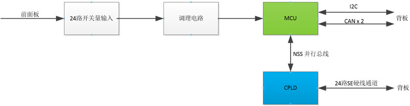
The board pairs two complementary devices to handle acquisition and communication:
CPLD — Altera EPM570T-144I3 The EPM570T is a 3.3 V MAX II CPLD from Intel/Altera, housed in a 144-pin TQFP package. With 570 logic elements and deterministic, non-volatile configuration, it is well-suited to glue logic, channel debouncing, and parallel-to-serial conversion tasks that would otherwise consume MCU cycles. In this design the CPLD acts as the front-end concentrator: it latches the 16 optocoupler outputs, performs any required channel-level filtering or timestamp capture, and presents a clean parallel or serial bus to the MCU. Because CPLD configuration is stored in internal flash (no external bitstream file required at power-up), the board is ready to sample immediately after the supply rails stabilize.
MCU — Freescale MC9S08DZ60 The MC9S08DZ60 is an 8-bit HCS08-core microcontroller from NXP (formerly Freescale), featuring 60 KB of in-circuit-programmable flash, 4 KB of RAM, a hardware CAN controller, and an I²C peripheral—exactly the communication mix this board exposes on its backplane connector. The MCU reads the channel state from the CPLD, packages it into CAN frames or I²C registers, and also runs the self-test routine that verifies signal-path integrity at power-on or on demand.
Power Supply Architecture
The board is powered from multiple rails drawn from the 3U chassis backplane:
| Rail | Typical Use |
|---|---|
| DC 5 V | Optocoupler LED drive, legacy logic |
| DC 3.3 V | CPLD core/IO, MCU IO |
| DC ±15 V | Analog conditioning (signal scaling, filtering) |
| DC ±24 V | Auxiliary field-side power or relay drive |
The presence of ±15 V and ±24 V rails suggests the board includes analog front-end conditioning—such as precision voltage dividers, clamping diodes, and possibly RC low-pass filters—before the optocoupler stage. This is good practice for 110 V DC environments where cable capacitance can cause slow edges and contact bounce from mechanical switches needs to be filtered in hardware before digital capture.
Communication Interfaces (Backplane Side)
The board exports its data through the 3U backplane connector using two protocols:
- CAN × 2: Two independent CAN 2.0B buses allow the board to participate in redundant or segmented fieldbus networks. Dual CAN is a common requirement in safety-related systems (e.g., IEC 61375 train communication networks) where a single point of failure on the communication path is unacceptable. The MC9S08DZ60's integrated MSCAN controller handles one bus; an external CAN controller or the second MSCAN instance handles the other.
- I²C × 1: A single I²C port is available for lower-bandwidth tasks such as reading board identity (EEPROM), interfacing to an onboard temperature sensor, or communicating with the chassis management controller for inventory and health monitoring.
Self-Test Capability
The board supports a self-test function—a meaningful feature for installed-base maintenance in railway and utility applications where field access is expensive. A typical implementation drives a known test pattern through the optocoupler stage (by stimulating the LED side with controlled current sources) and verifies that the CPLD captures the expected bit pattern. Any channel that fails to toggle correctly can be flagged over CAN, allowing ground staff to identify a faulty card or a broken field connection without removing the chassis from service.
Functional Block Diagram
Environmental and Mechanical Ratings
| Parameter | Value |
|---|---|
| Operating Temperature | −25 °C to +70 °C |
| PCB Dimensions | 220 mm × 100 mm × 1.6 mm |
| Weight | 0.165 kg |
| Form Factor | 3U |
The −25 °C to +70 °C operating range covers trackside enclosures in temperate climates and indoor substation equipment rooms without the need for active heating or forced air cooling. The 3U mechanical form factor is compatible with standard Eurocard/VME chassis, making the board easy to integrate into existing infrastructure.
Summary
This CPLD + MCU DI acquisition board illustrates a clean division of labor that is common in high-channel-count industrial I/O: the CPLD handles deterministic, parallel front-end sampling while the MCU manages protocol-aware communication and supervisory functions. The choice of DC 110 V input compatibility, dual CAN backplane connectivity, and an onboard self-test function reflects the reliability and interoperability demands of railway and power-utility deployments. Engineers evaluating this card for a new chassis design should verify that their backplane can supply all four power rails and that their network master supports the CAN baud rate and frame format used by the board's firmware.