FPGA-based 3U Chassis PT100 Temperature Acquisition Board for Rail Transit, Power Energy Storage, and Similar Applications
Accurate temperature monitoring is a non-negotiable requirement in rail transit propulsion systems, grid-side power energy storage cabinets, and industrial drive enclosures. This post covers a 3U chassis-mountable PT100 temperature acquisition board built around FPGA-based signal conditioning, designed to read up to eight PT100 resistance temperature detectors (RTDs) simultaneously and deliver calibrated 4–20 mA current loop outputs directly to a host processor or PLC.
Why PT100 RTDs for Industrial Temperature Sensing
PT100 is a platinum RTD whose resistance is nominally 100 Ω at 0 °C and follows a well-characterised positive temperature coefficient curve defined by the IEC 60751 standard. Compared with thermocouples, PT100 sensors offer better long-term stability, higher repeatability, and immunity to the cold-junction compensation errors that plague thermocouple circuits. The trade-off is that the sensor's resistance change per degree is small (roughly 0.385 Ω/°C in the industrial range), which demands careful signal conditioning to resolve sub-degree differences over long cable runs in electrically noisy environments such as traction substations or battery-string enclosures.
The board targets a nominal measurement range of −50 °C to +200 °C, which covers the full operating envelope of most power semiconductors, battery cell housings, traction motor windings, and transformer oil temperatures found in rail and energy-storage applications.
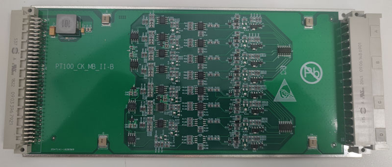
Board Overview
The board functions as a dedicated temperature front-end: each PT100 channel is excited with a precision constant-current source, the resulting voltage across the sensor is amplified and filtered, and the conditioned analogue signal is converted to a 4–20 mA current loop that is immune to voltage drops and common-mode noise over the cable back to the host backplane. The FPGA fabric handles channel multiplexing, excitation sequencing, and any linearisation or offset correction required to maintain the stated accuracy across the full temperature span.
Performance Specifications
| Parameter | Value |
|---|---|
| Power supply | DC 5 V logic rail; DC ±15 V analogue rail |
| 4-wire PT100 channels | 7 |
| 3-wire PT100 channels | 1 |
| Measurement range | −50 °C to +200 °C (all channels) |
| Output signal (conditioned) | 4–20 mA (corresponding to full measurement range) |
| Accuracy | ±0.5 °C |
| Board dimensions | 220 mm × 100 mm × 1.6 mm |
| Weight | 0.155 kg |
| Operating temperature | −25 °C to +70 °C |
4-Wire vs. 3-Wire PT100 Wiring
The board supports both connection topologies, which matters in practice:
4-wire (Kelvin) connection — used for the seven primary channels — eliminates lead-resistance error entirely. Two wires carry the excitation current; two separate sense wires measure the voltage directly across the sensor element. Because no current flows through the sense leads, their resistance contributes zero measurement error. This is the preferred topology whenever cable runs exceed a few metres or when the ±0.5 °C accuracy budget must be met without calibration offsets.
3-wire connection — used for the single auxiliary channel — provides a practical compromise when a fourth conductor is unavailable. The conditioning circuit measures the resistance of one lead and subtracts it symmetrically, assuming the two current-carrying leads are matched. This assumption holds well for most industrial cable assemblies, making 3-wire an acceptable choice for shorter or matched-pair runs while still achieving the rated ±0.5 °C accuracy.
Signal Conditioning and the 4–20 mA Current Loop
Converting RTD resistance to a 4–20 mA output is a deliberate architectural choice for industrial deployments. Current loops are inherently ratiometric — the receiver measures current, not voltage — so resistive drops along the signal cable are irrelevant as long as sufficient compliance voltage is available. The 4 mA live-zero also distinguishes a valid "sensor at minimum range" reading from a broken wire (0 mA), which gives the host system a built-in open-circuit fault indicator with no additional circuitry.
The dual supply (DC 5 V for the FPGA and digital logic, DC ±15 V for the analogue front end) is typical of precision current-loop transmitter designs: the split rail provides the headroom needed to drive the output current across a wide load impedance while keeping the sensitive amplifier stages in their linear region throughout the temperature range.
Functional Block Diagram
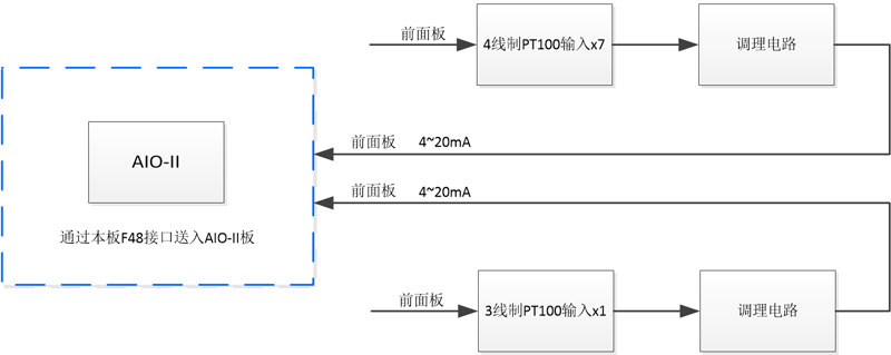
The functional block diagram illustrates the signal path from the PT100 terminals through excitation current generation, differential amplification, analogue-to-digital conversion inside the FPGA subsystem, and finally the voltage-to-current (V/I) output stage that drives the 4–20 mA loop on each channel.
Mechanical and Environmental Ratings
At 220 mm × 100 mm × 1.6 mm the board fits within a standard 3U Euro-card envelope, making it straightforward to slot into existing 19-inch rack chassis used in traction control cubicles and energy-storage battery management enclosures. The 0.155 kg mass is well within the card-cage weight limits typical of rail-certified equipment.
The operating temperature range of −25 °C to +70 °C is important: it ensures the board itself can function during cold-soak startup of rolling stock in winter climates or inside outdoor energy-storage containers, while the +70 °C upper limit provides margin above the maximum expected enclosure ambient in summer operation near power electronics.
Typical Application Scenarios
- Rail transit — monitoring motor bearing temperatures, brake resistor temperatures, and traction converter heatsink temperatures along a trainset, where long cable runs and heavy electromagnetic interference from propulsion inverters make 4–20 mA transmission essential.
- Grid-scale power energy storage — cell string temperature mapping in lithium-ion or flow battery systems, where ±0.5 °C accuracy is needed for safe charge/discharge management and cell balancing algorithms.
- Industrial drives and UPS — continuous heatsink and transformer winding monitoring in variable-frequency drives or uninterruptible power supplies installed in industrial automation cabinets.
In all these environments, the combination of FPGA-driven multi-channel RTD excitation, galvanically isolated 4–20 mA outputs, and a compact 3U form factor makes this board a practical drop-in acquisition front-end for existing backplane architectures without requiring custom analogue circuitry at the system level.