Rail Transit DSP+FPGA Main Control Board (6U) Supporting Logic Control, Data Processing, Communication Management, System Safety Protection Switching, and Other Functions
Rail transit control systems demand hardware that is simultaneously deterministic, fault-tolerant, and able to bridge high-speed optical interconnects with rugged field-bus protocols — all within the tight mechanical envelope of a 6U CompactPCI chassis. This post walks through the architecture and interface complement of a production-grade DSP+FPGA main control board designed specifically for that application, covering its logic-control role, communication topology, safety-switching capability, and the engineering trade-offs embedded in its specification.
Role of the Main Control Board
In a rail-transit electronic control unit (ECU) rack, the main control board is the system's nerve center. It owns four distinct responsibilities:
- Logic control — executing deterministic, scan-cycle control logic that governs traction, braking, door, and auxiliary subsystems.
- Data processing — aggregating sensor data from I/O modules, running diagnostics, and computing set-points for downstream actuator boards.
- Communication management — arbitrating traffic across a heterogeneous mix of optical, Ethernet, RS-485, and CAN buses that connect on-board equipment to the vehicle network and wayside infrastructure.
- System safety-protection switching — detecting fault conditions and triggering safe-state transitions (e.g., cutting traction, enabling redundant paths) fast enough to satisfy EN 50128 / IEC 61508 timing requirements.
A single board handling all four functions keeps the inter-subsystem latency low (on-chip or intra-rack signalling) and simplifies the certification boundary compared with distributing these roles across multiple cards.
FPGA Selection: Xilinx Artix-7 XC7A100T
The XC7A100T-2FGG484I is a mid-range Artix-7 device in a 484-ball FBG package with the industrial-grade temperature rating (-I suffix, −40 °C to +100 °C junction). Its key resources — approximately 101 K logic cells, 135 DSP48E1 slices, 4.86 Mb of block RAM, and 16 GTX transceivers capable of up to 6.6 Gb/s line rate — make it well suited for:
- Implementing the Aurora 64B/66B serial links used on the backplane (see below).
- Bridging the high-density LVDS parallel bus to the CPCIe fabric.
- Offloading deterministic I/O scanning from the DSP so that the processor core is free for application-level logic.
The -2 speed grade provides the timing margin needed to run multi-gigabit serial interfaces without resorting to the costlier -3 grade parts, keeping the BOM cost appropriate for volume rail production.
Power Architecture
The board accepts three supply rails directly from the backplane:
| Rail | Typical consumer |
|---|---|
| DC 5 V | DSP core logic, general digital |
| DC 3.3 V | FPGA I/O banks, LVDS termination, flash |
| DC 12 V | SFP module bias, isolated CAN/RS-485 transceivers |
Multi-rail supply rather than on-board DC-DC conversion from a single rail reduces switching noise that could couple into the high-speed serial transceivers, and it simplifies the power-sequencing design required for FPGA devices (I/O banks must not be powered before the core).
Storage Subsystem
Two non-volatile memories serve different roles:
- EEPROM 256 kb (DSP side) — used for storing configuration parameters, calibration tables, and application-layer persistent state. EEPROM is preferred over flash here because it supports byte-granular in-system writes without erase cycles, making it suitable for frequent, small writes (e.g., trip counters, fault logs).
- Flash 256 kb (FPGA side) — holds the FPGA bitstream for configuration on power-up. Xilinx Artix-7 SPI configuration mode is the typical implementation; the small capacity reflects the compressed bitstream size for a 100T device.
Communication Interfaces
Front-Panel Side
The panel-facing connectors expose the board to vehicle-level networks and diagnostic tooling:
| Interface | Count | Notes |
|---|---|---|
| RS-485 | 1 | Half-duplex, legacy sensor/actuator networks |
| CAN | 1 | CANopen or TRDP-mapped vehicle network |
| SFP (2.125 Gb/s) | 1 | Fibre-channel-rate optical; likely Aurora or proprietary protocol |
| SFP (1.0625 Gb/s) | 2 | Fibre-channel half-rate; redundant optical paths |
| SFP (100 Mb/s) | 1 | Ethernet-over-fibre for managed Ethernet switch ports |
| ETH (100 Mb/s) | 1 | Copper RJ-45 for maintenance laptop / TRDP |
The three SFP optical ports at different line rates reflect a common rail practice: separate links for safety-critical control data (the 2.125 G port, running a deterministic protocol), redundant inter-vehicle consist links (the two 1.0625 G ports), and a best-effort Ethernet path for diagnostics and software download.
Backplane Side
The backplane interface is where the board integrates into the 6U CompactPCI chassis:
| Interface | Count | Notes |
|---|---|---|
| LVDS | 90 lines | Parallel high-density I/O to adjacent I/O modules |
| CPCIe | 1 | CompactPCI Express system slot — main chassis fabric |
| Aurora | 2 | Xilinx Aurora 64B/66B links for high-throughput board-to-board data |
| RS-485 | 1 | Backplane-routed fieldbus |
| I²C | 1 | Board management, IPMI-style health monitoring |
| CAN | 1 | Intra-chassis safety bus (redundant path) |
| IO HardWire | 32 | Direct discrete I/O for hard real-time safety signals |
The 90-line LVDS bus is particularly notable: at LVDS signalling rates this bus can sustain hundreds of megabits per second of parallel I/O data without the latency overhead of a packet-switched fabric, which is essential for the cycle-accurate sensor sampling that logic control requires. The 32 hardwired I/O lines complement this by providing guaranteed-latency paths for the most safety-critical discrete signals (e.g., emergency stop, door-open interlock) that must not traverse any software stack.
Mechanical and Environmental Specifications
| Parameter | Value |
|---|---|
| Dimensions | 160 mm × 233.5 mm × 1.6 mm |
| Weight | 0.175 kg |
| Operating temperature | −25 °C to +70 °C |
The 160 × 233.5 mm footprint matches the 6U Eurocard form factor (233.35 mm height per IEC 60297). At 1.6 mm PCB thickness, the board is a standard rigid-stack construction — sufficient for the layer count needed to route 90 LVDS pairs and multiple GTX transceiver traces with controlled impedance. The −25 °C to +70 °C operating range covers the ambient conditions inside a locomotive or EMU equipment cabinet, including cold-soak at winter start-up and elevated temperatures in summer in high-power density racks.
Functional Block Diagram
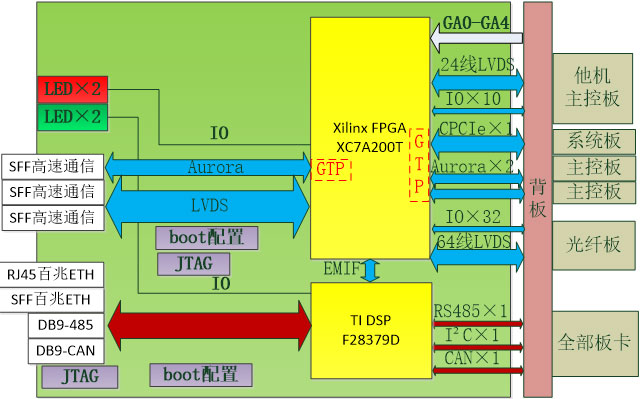
The block diagram illustrates how the FPGA acts as a crossbar between the three major domains: the optical/Ethernet front-panel network, the CPCIe/Aurora/LVDS backplane fabric, and the hard-wired safety I/O. The DSP communicates with the FPGA over a dedicated high-speed local bus, delegating I/O scanning and protocol framing to the FPGA while retaining application-layer control logic and communication management in software.
Summary
This 6U main control board exemplifies the hardware architecture that modern rail transit demands: a deterministic FPGA fabric for I/O and serial-link offload, a DSP for application logic, a carefully partitioned mix of optical and fieldbus interfaces, and hard-wired safety I/O paths that remain independent of software. The Artix-7 XC7A100T provides the transceiver count and logic density to implement all three optical SFP links plus the two Aurora backplane channels in a single device, keeping the board compact and the BOM manageable for a product that must achieve multi-year service life in rolling stock.