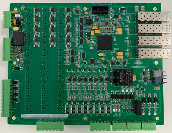
FPGA-based CPCI Pulse Board for Rail Transit 6U Chassis
Rail transit drive systems demand extreme reliability, deterministic timing, and immunity to electrical noise — requirements that make FPGA-based control hardware the natural choice over general-purpose microcontrollers. This post covers Sienovo's FPGA-based CPCI Pulse Board for 6U chassis deployments, detailing its architecture, signal chain, and the engineering rationale behind its key design choices.
What a Pulse Board Does in a Traction Drive System
In a rail transit variable-frequency drive (VFD) system, the pulse board sits between the host CPU (typically running a supervisory control application on a companion processor board) and the inverter power module that drives the traction motors. Its job is tightly scoped but timing-critical:
- Receive control commands from the CPU over the backplane bus.
- Execute control algorithms — typically field-oriented control (FOC) or direct torque control (DTC) — to compute the required PWM duty cycles and switching patterns.
- Generate PWM outputs with precise dead-time insertion to prevent shoot-through in the inverter bridge.
- Transmit PWM commands as optical fiber signals to the gate-drive boards on the power module, isolating the low-voltage logic side from high-voltage power electronics.
The optical fiber link is not incidental: rail environments expose electronics to severe conducted and radiated EMI from traction current switching. Fiber eliminates ground loops and provides galvanic isolation across the high-voltage boundary, which is a safety and regulatory requirement in IEC 61375 / EN 50155 compliant rolling stock.
FPGA Selection: Xilinx Artix-7 XC7A100T
The board uses the XC7A100T-2FGG484I — a member of Xilinx's Artix-7 family housed in a 484-ball fine-pitch BGA package. Key attributes relevant to this application:
- 100K logic cells with dedicated DSP48E1 slices for fixed-point arithmetic, well-suited to real-time execution of PWM modulation algorithms (SVPWM, SPWM) without floating-point overhead.
- -2 speed grade provides deterministic propagation delays, important when generating symmetrical PWM with sub-microsecond dead-time accuracy.
- Industrial temperature variant (-I suffix): rated from −40 °C to +100 °C junction temperature, covering the board's operating range with margin.
- Integrated GTP transceivers capable of supporting multi-gigabit serial links — directly enabling the on-board SFP interfaces without external SerDes silicon.
Using an FPGA rather than a DSP or MCU means the PWM generation, encoder feedback processing, protection logic (overcurrent, overvoltage, gate-fault), and communication stacks all run in parallel hardware — not sequentially in software. This eliminates jitter sources that would otherwise degrade current-loop bandwidth.
Power Supply Architecture
The board accepts DC 5V for digital logic and ±15V for analog front-end circuitry. The dual analog rail is characteristic of precision signal conditioning: op-amp stages for current and voltage sensing perform better with symmetric supplies, and ±15V headroom accommodates the full input range of industrial sensors without clipping. On-board regulators step these rails down to the 1.0 V core, 1.8 V I/O, and 3.3 V auxiliary voltages required by the FPGA fabric and peripherals.
Storage: 256 Mb NOR Flash
The 256 Mb (32 MB) NOR Flash serves as non-volatile configuration storage. At power-on, the FPGA loads its bitstream from NOR Flash via a master SPI or BPI interface. NOR Flash is chosen over NAND here because it supports execute-in-place (XiP) and has a far lower bit-error rate — important when a corrupted bitstream could cause a fail-to-start on a revenue train. The capacity comfortably holds the FPGA bitstream plus any parameter tables or calibration data for the analog front end.
Communication Interfaces
Backplane Side
- RS-485 × 1: a robust differential bus for command/status exchange with the CPU board across the CPCI backplane. RS-485's common-mode noise rejection suits the electrically harsh interior of a drive cabinet.
- I²C × 1: typically used for board management functions — reading temperature sensors, EEPROM configuration data, or power-supply status registers.
Front Panel Side
- SFP (2.125 Gbps) × 2 + SFP (2.125 Gbps) × 2: four SFP cages wired to the FPGA's GTP transceivers. The 2.125 Gbps rate is consistent with Fibre Channel 2x or custom industrial protocols. These high-speed links likely carry real-time data (e.g., encoder feedback, inter-board synchronization) or serve as uplink ports to a consist-level network.
Optical PWM Outputs
24 pairs of optical transceivers carry the gate-drive PWM signals to the inverter. A three-level NPC (Neutral Point Clamped) inverter for a three-phase motor requires six gate signals per phase leg switch; 24 pairs provides capacity for a multi-level or multi-motor topology, plus redundant or auxiliary channels.
Analog Signal Acquisition
The board integrates 5 channels of analog voltage acquisition and 3 channels of analog current acquisition. In a traction drive context these typically measure:
- Voltage channels: DC-link voltage, phase voltages, auxiliary bus voltages — inputs to the protection and modulation algorithms.
- Current channels: phase currents for the motor model (FOC requires at least two phase current measurements; three provides redundancy and permits zero-sequence detection).
These analog signals are conditioned, level-shifted to the FPGA's ADC-compatible range, and sampled synchronously with the PWM carrier to minimize switching noise aliasing — a standard technique in motor drive design.
Mechanical and Environmental Specification
| Parameter | Value |
|---|---|
| Form factor | 6U CPCI (CompactPCI) |
| PCB dimensions | 160 mm × 233.5 mm × 1.6 mm |
| Weight | 175 g |
| Operating temperature | −25 °C to +70 °C |
| Power supply | DC 5V; ±15V |
The 6U CompactPCI form factor is a well-established standard in railway and defense electronics, providing passive backplane connectivity, robust card-edge ejector handles, and compatibility with IEC 60297 subrack dimensions. The −25 °C to +70 °C operating range covers typical under-floor equipment compartments on metro and light-rail rolling stock without requiring forced air cooling at the board level.
Functional Block Diagram
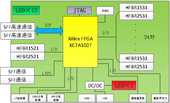
The block diagram illustrates the data flow from backplane command reception through FPGA-internal algorithm execution to optical PWM output, along with the analog acquisition feedback paths that close the control loop.
Summary
This FPGA-based CPCI pulse board addresses the core challenges of rail traction control: deterministic PWM generation, galvanic isolation across high-voltage boundaries via fiber optics, and robust communication in an EMI-intensive environment. The Artix-7 XC7A100T provides sufficient logic density and DSP resources for parallel execution of protection, modulation, and communication tasks, while the NOR Flash, dual-rail analog supply, and wide operating temperature range reflect the reliability and environmental demands of rolling-stock deployments.