NXP+FPGA+QNX-Based Rail Transit 6U Chassis Vehicle Control Unit (VCU)
Modern rail transit systems demand onboard intelligence that can handle real-time control, safety-critical decision-making, and comprehensive diagnostics — all within the harsh vibration, temperature, and EMI environment of a moving train. The NXP+FPGA+QNX-based 6U chassis Vehicle Control Unit (VCU) described here is purpose-built for exactly that role. This post walks through the architecture, application scope, communication interfaces, I/O capabilities, and operating envelope of this platform, giving engineers a clear picture of where and how it fits into a modern rail vehicle network.
What Is a VCU and Why Does It Matter?
The Vehicle Control Unit sits at the top of a train's onboard control hierarchy. Unlike individual subsystem controllers — which manage a single door module or a single HVAC zone — the VCU provides train-wide supervisory control and diagnostics. It aggregates data from every major subsystem, executes high-level control logic, and serves as the primary gateway between the train and ground-side systems.
The combination of an NXP application processor, an FPGA co-processor, and a QNX real-time operating system is a deliberate architectural choice. NXP's industrial-grade SoCs (such as the i.MX or Layerscape families) offer the processing headroom needed for fleet management logic and HMI rendering. The FPGA handles deterministic, low-latency I/O tasks — counting encoder pulses, managing relay timing, or bridging legacy fieldbus protocols — where a general-purpose CPU scheduler would introduce unacceptable jitter. QNX provides a POSIX-compliant, microkernel RTOS with a well-established safety pedigree, making it a natural fit for applications targeting IEC 61508 SIL certification.
Application Scope
A single VCU can govern a broad set of train subsystems simultaneously. Documented application areas include:
- Diagnostics — Continuous health monitoring of connected subsystems, fault logging, and event-driven alerting accessible from the crew HMI or ground systems.
- PIS/PA System Management — Coordinating passenger information displays and public address announcements with station stop schedules and operational events.
- Crew HMI Management — Serving as the backend for the driver/conductor interface, routing alarms, operating modes, and override commands.
- Braking and Traction Monitoring — Reading brake pressure sensors, wheel speed data, and traction inverter status; detecting anomalies before they escalate to failures.
- SIL and Safety Applications — Supporting safety-integrity-level workflows where specific I/O channels and watchdog logic must meet defined failure rates.
- Fleet Management — Collecting mileage, energy consumption, fault history, and maintenance counters for upload to depot systems.
- HVAC Management — Regulating heating, ventilation, and air-conditioning zones based on occupancy, ambient temperature (via Pt-100 sensors), and schedule.
- Door Management — Physical control of opening, closing, and locking door leaves, along with status monitoring to confirm proper closure before departure clearance.
- Lighting Management — Switching interior and exterior lighting circuits, including emergency and night-mode profiles.
- CCTV System Management — Triggering camera recording events, managing video stream routing, and storing incident clips.
- Water Tank Level Monitoring — Tracking potable and waste water levels through analog sensors.
- Battery Charge Monitoring — Supervising auxiliary battery state-of-charge and charger health.
- Train-to-Ground Communication Management — Handling the link layer between onboard systems and wayside servers over TRDP/ETB, including session management and failover.
The breadth of this list reflects a key design principle: consolidating what might otherwise be a dozen separate controllers into a single, maintainable 6U chassis unit reduces wiring complexity, cabinet space, and the number of single-points-of-failure in the overall system architecture.
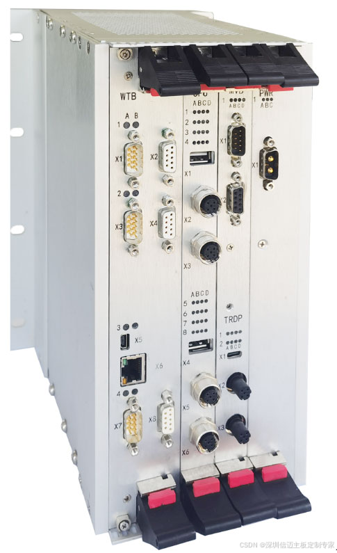
Communication Interfaces
Interoperability with the existing train communication network is handled through a rich set of bus interface modules:
| Protocol | Role in Rail Systems |
|---|---|
| WTB (Wire Train Bus) | IEC 61375 train-level backbone; carries consist control and vehicle identity data |
| MVB (Multifunction Vehicle Bus) | IEC 61375 vehicle-level bus; real-time process data exchange between subsystems |
| CAN | Cost-effective link to lower-tier controllers (door drives, HVAC units, battery chargers) |
| TRDP (Train Real-time Data Protocol) | Ethernet-based, IEC 61375-2-3 compliant; increasingly replacing WTB/MVB in new builds |
| ETB (Ethernet Train Backbone) | High-bandwidth backbone for video, diagnostics, and IP-based services |
| Serial links | Legacy point-to-point interfaces for older subsystem controllers |
Supporting all five major rail fieldbus standards from one chassis means the VCU can be deployed on brownfield fleets that still carry WTB/MVB wiring, as well as on next-generation Ethernet-based consists, without swapping hardware.
I/O Capabilities
Beyond network connectivity, the VCU provides direct hardware I/O through plug-in interface modules:
- Analog input — General-purpose voltage/current channels for sensors such as pressure transducers and level transmitters.
- High-speed analog input — For signals requiring faster sampling rates, such as vibration or current waveform capture.
- Digital input/output — Discrete signals for limit switches, indicator lamps, and control outputs.
- Digital relay output — Electrically isolated relay contacts for switching higher-voltage or higher-current loads (door locks, lighting contactors).
- Analog output — Voltage or current command signals to actuators and setpoint inputs on third-party controllers.
- Pt-100 temperature sensor input — Direct RTD interface eliminates the need for separate signal-conditioning transmitters in HVAC and brake thermal monitoring applications.
Remote Input/Output Modules (RIOMs) extend this reach to areas of the train physically distant from the main VCU chassis, connected back over the vehicle bus — a standard pattern in long consists where running home-run cables to every sensor is impractical.
Technical Specifications
| Parameter | Value |
|---|---|
| Form factor | 6U chassis |
| Dimensions (W × H × D) | 112 mm × 266 mm × 190 mm |
| Weight | 5 kg |
| Input voltage | 110 V DC |
| Operating temperature | –25 °C to +70 °C |
| Supported networks | TRDP / MVB / CAN / WTB / ETB |
The 110 V DC supply rail is standard on European and many Asian heavy-rail vehicles, fed from the main battery bus. The –25 °C to +70 °C operating range covers arctic-to-desert climate zones without derating, consistent with EN 50155 railway rolling stock electronics requirements. At 5 kg and under 200 mm deep, the unit is compact enough to fit inside standard trackside or underfloor equipment cabinets without consuming the space of a legacy rack system.
Where This Platform Fits in Your Design
For system integrators evaluating onboard control architectures, the NXP+FPGA+QNX VCU occupies the supervisory tier — above individual actuator controllers but below the central train management system (TMS). Its combination of deterministic FPGA I/O, the processing power of an NXP application processor, and QNX's real-time scheduling makes it well-suited to applications where mixed-criticality workloads (safety-critical relay logic alongside non-critical fleet telemetry) must coexist on the same hardware. The modular bus interface approach also provides a practical migration path: operators can begin with CAN and MVB modules on existing fleets and add TRDP/ETB modules as network upgrades roll out across the consist.