FPGA-based 3U Rail Transit Network Communication Board: Internal Communication with Main Control and I/O Boards, External RS485, CAN, or MVB Networking
Overview
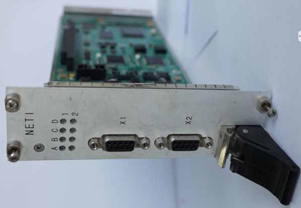
The NETI (Network Interface Board) is a 3U-format FPGA-based communication card designed for rail transit control systems. Positioned as the communication hub within a modular control rack, it bridges internal backplane traffic — carrying data to and from the main control board and distributed I/O boards — while simultaneously managing external field-bus connections to trackside equipment, other vehicles, or wayside controllers. This post walks through the board's architecture, component choices, and the role each interface plays in a typical rail transit installation.
Role in a Rail Transit Control Rack
Modern rail traction and auxiliary control systems are built around a backplane-based, card-cage architecture. A typical rack contains a main control board (CPU/MCU), multiple I/O boards handling discrete signals, analog measurements, and relay outputs, plus one or more communication boards like this NETI card. The NETI acts as the protocol translator and traffic concentrator: it aggregates data from all the I/O boards over the backplane bus, packages it for the main controller, and simultaneously exposes standard industrial fieldbus ports to the outside world.
This separation of concerns — compute on the main board, I/O on daughter cards, networking on a dedicated NETI — keeps each card's responsibility narrow, simplifies certification under railway standards such as EN 50155 or IEC 61375, and allows the communication stack to be updated or swapped without touching the control logic.
Key Components
FPGA: Xilinx Spartan-6 XC6SLX25-2FG484I
The XC6SLX25 is a mid-range device from Xilinx's Spartan-6 family, housed in a 484-ball Fine-Pitch BGA package. With approximately 24,000 logic cells, 38 DSP48A1 slices, and integrated block RAM, it provides ample fabric to implement custom communication controllers, data buffering, and glue logic without relying on external ASICs. The -2 speed grade and I (industrial) temperature suffix confirm suitability for the −25 °C to 70 °C operating range specified. In this design the FPGA most likely implements the backplane bus controller, arbitrates access between the two MCUs, and may host a soft-core MVB (Multifunction Vehicle Bus) controller when that option is populated.
The 16 MB PROM provides non-volatile configuration storage for the FPGA bitstream, allowing the board to self-configure at power-on without host intervention — a common requirement in safety-relevant embedded systems where a cold-start must be fully autonomous.
MCU: NXP (Freescale) MK60DN512VLL10 × 2
The MK60DN512 is a member of the Kinetis K60 family, based on an ARM Cortex-M4 core running at up to 100 MHz, with 512 KB of on-chip flash and a rich peripheral set including multiple CAN controllers, UARTs, SPI, and I²C. Using two of these MCUs in parallel is a common pattern in railway electronics: one MCU typically handles the external-facing fieldbus stack (CAN, RS485 framing, MVB if fitted), while the second manages internal housekeeping, health monitoring, and the backplane I²C links. The dual-MCU topology also supports redundancy or cross-checking schemes required by SIL-rated designs.
CPLD: Intel (Altera) EPM570T100I5N
The EPM570 is a MAX II CPLD with 570 logic elements in a 100-pin TQFP, rated to the industrial temperature range. CPLDs in mixed-signal embedded designs typically handle board-level sequencing, power-on reset glue, bus arbitration signals, and interface-level voltage translation — tasks that would waste FPGA fabric or MCU GPIO. Here it likely manages power sequencing between the 5 V and 3.3 V rails and acts as a supervisory gatekeeper during startup.
Communication Interfaces
Panel-Side (External Field Connections)
| Interface | Connector | Quantity | Notes |
|---|---|---|---|
| CAN | D-SUB 9 | 2 | ISO 11898, standard pinout |
| RS485 | D-SUB 9 | 2 | Half-duplex, multi-drop |
| MVB | D-SUB 9 | 2 | Optional, IEC 61375-1 |
CAN (Controller Area Network) is ubiquitous in rail auxiliary systems — door controllers, HVAC units, and battery management systems routinely speak CANopen or a proprietary CAN-based protocol. Two independent CAN channels allow the NETI to sit on two separate field segments simultaneously, useful when the vehicle network is partitioned by subsystem.
RS485 remains the workhorse for lower-bandwidth, longer-cable runs. Its differential signaling tolerates the high-EMI environment inside a rail vehicle, and half-duplex multi-drop wiring keeps cabling cost low. The dual RS485 ports can serve separate device groups or provide a primary/redundant link arrangement.
MVB (Multifunction Vehicle Bus), standardised in IEC 61375-1, is the train-specific fieldbus defined for WTB/MVB-based consist networking — the same bus used by traction converters, brake controllers, and the Train Management System (TMS) in many European and Chinese EMU/LRV platforms. Its inclusion as an option on this board indicates the design targets interoperability with existing MVB-equipped rolling stock without forcing all customers to pay for MVB silicon when a simpler CAN or RS485 topology suffices.
Backplane-Side (Internal Rack Communication)
| Interface | Quantity | Typical Use |
|---|---|---|
| CAN | 1 | High-level backplane data exchange |
| I²C | 4 | Board ID, sensor readout, health monitoring |
The single backplane CAN port connects the NETI to the main control board and peer I/O cards within the same rack, providing a structured, priority-based message bus for real-time data exchange. The four I²C links are lower-bandwidth but extremely lightweight to implement; they are well-suited for reading temperature sensors, board identification EEPROMs, and voltage monitor ICs scattered across the rack — tasks that would be wasteful to route through the main CAN segment.
Power and Mechanical Specifications
The board runs from dual supply rails — DC 5 V for legacy TTL-level logic and CAN/RS485 transceivers, and DC 3.3 V for the FPGA core, MCUs, and CPLD. Both rails are typically supplied by a centralised backplane power module, keeping the NETI itself free of bulky DC-DC converters.
At 220 mm × 100 mm × 1.6 mm and 160 g, the board conforms to the 3U Eurocard footprint, making it mechanically compatible with standard 19-inch sub-rack systems widely used in rolling-stock electronics enclosures. The −25 °C to 70 °C operating range exceeds the EN 50155 Class TX requirement (−40 °C to 70 °C cold-soak, 70 °C continuous operation), covering under-floor and cab-equipment-bay installations in most climate zones.
Functional Block Diagram
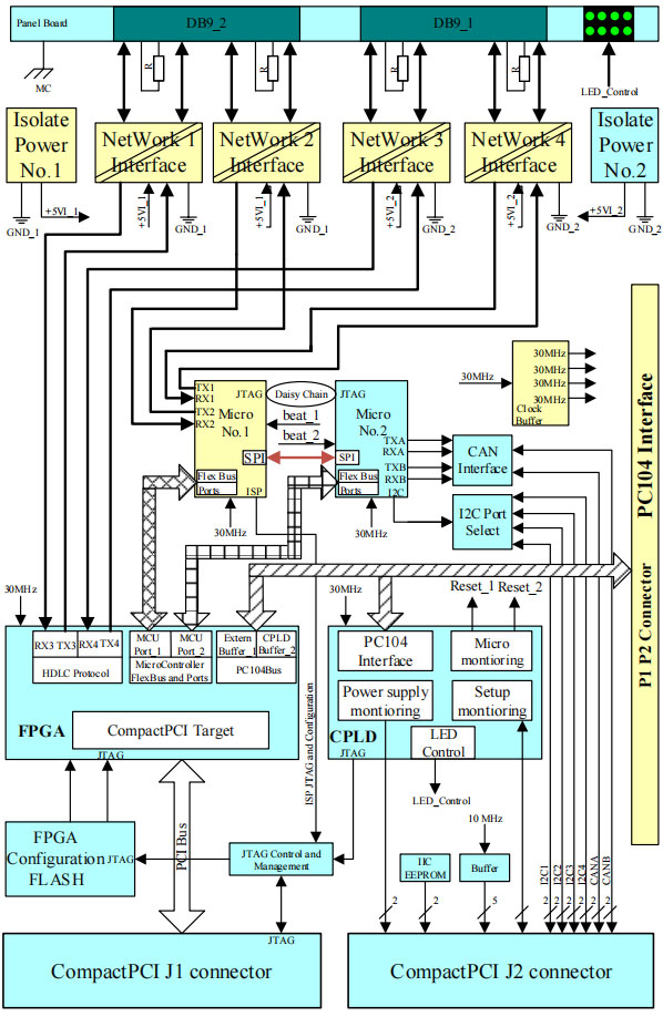
The block diagram illustrates the central role of the FPGA as the routing fabric, with the two MCUs handling the fieldbus stacks on either side and the CPLD providing supervisory glue. The backplane CAN and I²C buses feed in from the left (rack side), while the panel connectors for CAN, RS485, and optional MVB face outward toward the field.
Design Considerations and Use Cases
Because the NETI offloads all communication protocol handling from the main control board, the latter can run a deterministic real-time control loop without being interrupted by bus traffic management. This is a significant advantage in safety-relevant applications where jitter in the control cycle must be bounded.
The optional MVB population strategy also deserves note: by designing the PCB to accept MVB transceiver ICs and FPGA bitstream variants that implement the MVB controller, the manufacturer can serve both MVB-equipped legacy fleets and newer CAN/RS485-only platforms from a single board design — reducing qualification overhead and spare-parts inventory for operators running mixed fleets.
For system integrators, the four I²C backplane links offer a convenient out-of-band health channel: even if the main CAN bus is saturated or under fault recovery, the I²C network can still report board temperatures, supply voltages, and error counters to the main controller, supporting predictive maintenance and fault isolation workflows.