CPLD-Based Digital Output (DO) Board for Power/Rail Transit 3U Chassis
This board is a 14-channel digital output (DO) card designed for 3U chassis deployments in power and rail transit applications. It combines a Freescale MC9S08DZ60 microcontroller, an Altera EPM570T CPLD, and solid-state relays to deliver robust, optically isolated switching suitable for the demanding electrical environments found in traction power substations and train control cabinets. This post covers the board's architecture, key component choices, and the design rationale behind its specification.
Application Context
Power and rail transit systems impose strict requirements on digital output hardware: wide operating temperature ranges, immunity to high-voltage transients, galvanic isolation between control logic and field loads, and deterministic behavior under fault conditions. A 3U CompactPCI or similar backplane chassis provides the mechanical and electrical framework, while individual function boards — like this DO card — plug in to perform specific I/O tasks. The DO board's role is to convert low-voltage logic commands from the host CPU into switched high-voltage drive signals for contactors, solenoid valves, indicator lamps, and other field devices.
Key Components
MCU: MC9S08DZ60
The Freescale (now NXP) MC9S08DZ60 is an 8-bit HCS08-core microcontroller with 60 KB flash, 4 KB RAM, and an integrated CAN controller. In this design it handles:
- Backplane communication — the MC9S08DZ60's dual CAN interfaces expose the board to the host system over two independent CAN buses, providing redundancy typical of safety-relevant transit applications.
- I2C management bus — a single I2C link allows the board to report diagnostic data (temperature, relay status, supply rail voltages) to a chassis management controller.
- Self-test sequencing — the MCU can exercise each output channel in a controlled manner and verify feedback paths without requiring the host CPU to intervene.
CPLD: EPM570T-144I3
The Altera EPM570T-144I3 (MAX II family) sits between the MCU and the solid-state relay drive circuitry. With 570 logic elements and a 144-pin TQFP package, it provides:
- Channel demultiplexing — translating the MCU's serial or parallel commands into 14 independent relay-drive signals.
- Glitch filtering and output latching — ensuring that transient bus noise does not cause spurious switching of high-voltage loads.
- Interlocking logic — enforcing mutual exclusion rules or sequencing constraints that would be difficult to guarantee purely in MCU firmware.
- Speed — CPLD combinatorial paths are deterministic and sub-microsecond, which matters when relay timing is safety-critical.
The "I3" speed-grade suffix and the industrial temperature rating of the EPM570T-144I3 are consistent with the board's -25 °C to +70 °C operating range.
Solid-State Relays and Output Stage
Each of the 14 output channels uses a solid-state relay (SSR) rather than an electromechanical relay. SSRs offer several advantages in transit environments:
- No moving parts — eliminates contact wear, making them suitable for high-cycle-rate applications.
- Optical isolation — the control side (3.3 V / 5 V logic) is fully isolated from the field side, blocking ground loops and high-voltage spikes from propagating into control electronics.
- Fast switching — typically microsecond-range turn-on/off, compared to milliseconds for mechanical relays.
The nominal high-level output is DC 110 V, which is the standard auxiliary supply voltage in many railway and power substation environments (derived from station battery systems). The low level is 0 V. The maximum continuous output current of 8 A per channel allows the board to directly drive medium-sized contactors or groups of indicator loads without an intermediate power stage.
Power Architecture
The board draws from five supply rails provided by the backplane:
| Rail | Typical Use |
|---|---|
| DC +5 V | MCU core, CPLD I/O, digital logic |
| DC +3.3 V | MCU I/O, CPLD core |
| DC +15 V | SSR control bias, analog front-end |
| DC -15 V | Differential signal conditioning |
| DC ±24 V | SSR drive stage or pre-drive power |
The multi-rail approach allows each functional block to operate at its optimal voltage while keeping switching noise on the high-voltage output stage from coupling back into the sensitive MCU and CPLD supplies.
Self-Test Capability
The self-test function is notable for a safety-critical board. Typically this involves:
- The MCU asserting each output channel in turn while monitoring a feedback signal (often a current-sense resistor or a secondary SSR status output).
- Comparing the measured response against expected thresholds.
- Reporting pass/fail status over the I2C management bus.
This allows automated board-level health checks at system power-up or during scheduled maintenance windows — a requirement in many transit signaling standards.
Physical Characteristics
At 220 mm × 100 mm × 1.6 mm and 305 g, the board conforms to a standard 3U Eurocard footprint. The 1.6 mm PCB thickness is the industry default, supporting robust backplane connector insertion forces. The -25 °C to +70 °C operating range covers typical indoor substation and trackside cabinet environments without requiring active cooling.
Functional Block Diagram
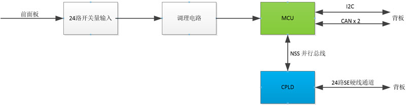
The block diagram illustrates the signal path from the backplane CAN/I2C interfaces through the MCU, into the CPLD for logic processing and latching, and finally through the SSR drive stage to the 14 field output terminals. The isolation barrier at the SSR boundary is the critical architectural feature that protects the logic side from the 110 V field environment.
Summary
This CPLD-based DO board is a well-structured design for harsh industrial and rail transit environments. The combination of the MC9S08DZ60's integrated dual-CAN connectivity, the EPM570T CPLD's deterministic output control, and solid-state relay isolation makes it a capable and reliable solution for high-voltage discrete output tasks in 3U chassis systems. The built-in self-test function and wide temperature rating further align it with the dependability expectations of power and transit infrastructure deployments.