ZYNQ Lidar-Visual SLAM Algorithm Porting and Design
This article details the development and implementation of a ZYNQ-based system for real-time 3D reconstruction, leveraging both FPGA-accelerated stereo vision and a LiDAR-based mobile platform. Readers will learn about the system's architecture, key algorithms like BM, SGBM, and ICP, hardware components including a Mecanum wheel robot and R-Fans-16 LiDAR, and its performance characteristics for environmental perception in applications like robotics and autonomous systems.
FPGA-Accelerated Stereo Vision on ZYNQ
The initial phase of this project focused on developing an FPGA-accelerated stereo vision system on a Xilinx ZYNQ platform for real-time 3D reconstruction. This involved a tight integration of the ZYNQ's Processing System (PS) and Programmable Logic (PL) for collaborative processing, enabling high-performance image processing tasks.
Key achievements in this stereo vision component include:
- Stereo Image Acquisition and PS+PL Processing: Successfully implemented the capture of stereo images, utilizing the ZYNQ's PS for control and higher-level tasks, and the PL (FPGA fabric) for accelerating computationally intensive image processing operations.
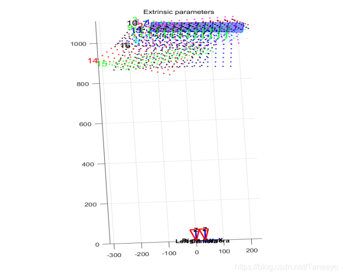
- Camera Calibration and Lens Correction: Developed and integrated routines for precise camera calibration and lens distortion correction directly on the ZYNQ platform. This is crucial for accurate 3D reconstruction, as it eliminates geometric distortions introduced by the camera lenses.
- Stereo Matching Algorithms: Implemented and optimized several stereo matching algorithms on ZYNQ. This currently includes both local stereo matching (Block Matching - BM) and semi-global stereo matching (Semi-Global Block Matching - SGBM), allowing for the computation of disparity maps from stereo image pairs.
- Depth Map and Rainbow Map Generation: After stereo matching, the system converts the generated disparity maps into real-time depth maps. These depth maps are further processed into "rainbow maps," which are colorized depth visualizations that provide an intuitive representation of scene depth.
- Ranging Algorithm: A ranging algorithm has been developed on ZYNQ to calculate distances. However, it currently lacks a recognition algorithm, meaning it can only compute the distance to a single specified point in the image. Despite this limitation, the system achieves an accuracy within 10mm, with an effective testing range of up to 5m.
- Algorithm Optimization: All implemented algorithms have undergone significant optimization. The system currently achieves near 720p image quality at a frame rate of approximately 30 frames per second, demonstrating its capability for real-time applications.
A dedicated series of articles is planned to detail the implementation process of this real-time 3D reconstruction project on ZYNQ, covering its development from scratch.
The Broader Context of 3D Reconstruction
In recent years, fields such as machine learning and autonomous driving have become prominent research areas, where environmental perception by computers is paramount. Consequently, 3D environment reconstruction is an essential trend, facilitating interaction between virtual and real worlds.
The two primary methods for 3D reconstruction are vision-based and LiDAR-based technologies. Vision-based ranging relies on triangulation, typically offering a maximum range of 5-8m, making it less suitable for larger spaces. It is also highly susceptible to lighting conditions. In contrast, LiDAR (Light Detection and Ranging) can be applied in a much wider array of scenarios due offering superior range and robustness to ambient light.
Sienovo's ZYNQ-based LiDAR 3D Modeling System
This article's primary focus is on a ZYNQ-based LiDAR 3D modeling system designed to address the challenges of environmental perception. This system aims to deeply explore target environments, collect point cloud data, reconstruct 3D spatial models, and support various machine vision applications such as measurement.
Application Areas
3D modeling has extensive applications across various domains:
- Drones and Autonomous Vehicles: Essential for real-time obstacle avoidance and path planning.
- Machine Vision and 3D Printing: Can be integrated with these technologies for advanced perception and manufacturing.
- Cultural Heritage Preservation: Significant for the replication and reconstruction of cultural relics.
- Environmental Survey: The system, mounted on a remote-controlled mobile platform, can survey environments inaccessible to humans.
Key Technical Features
The ZYNQ-based LiDAR 3D modeling system incorporates several distinguishing technical features:
- PCL ICP Algorithm: The system utilizes the Iterative Closest Point (ICP) algorithm from the Point Cloud Library (PCL) to perform multiple iterative calculations on LiDAR data, achieving precise point cloud registration.
- Integrated Mobile Platform: The LiDAR is mounted on a Mecanum wheel robot. The robot's gyroscope and motor encoders provide real-time position and velocity information. Through coordinate system transformations, this enables precise, real-time localization of the LiDAR sensor.
- Robust Indoor Reconstruction: This design enables real-time 3D reconstruction of indoor objects within a 1-5m range, with minimal blind spots. A significant advantage is its low susceptibility to lighting conditions, making it reliable in varied indoor environments.
- Remote Exploration: By deploying the LiDAR on a remotely controllable robot, the system can be used to survey environments that are hazardous or inaccessible to human operators.
Key Innovations
The system introduces several innovative aspects:
- Mobile App Remote Control: The Mecanum wheel robot can be controlled remotely via a mobile application, enhancing operational flexibility.
- PCL-based Algorithm Foundation: The core algorithms are built upon the robust and widely-used PCL point cloud library.
- Real-time Data Registration: Achieves real-time data registration through the efficient implementation of the ICP algorithm.
- HLS Acceleration on PYNQ: The ICP algorithm benefits from High-Level Synthesis (HLS) acceleration on the Programmable Logic (PL) module of the PYNQ-Z2 development board, significantly boosting computational speed.
System Composition and Functionality
Overall Introduction
The system comprises three main components: the LiDAR sensor, a Mecanum wheel robot based on an STM32 microcontroller, and a Xilinx PYNQ-Z2 development board.
- LiDAR Data Transmission: The LiDAR transmits collected point cloud data to the PYNQ-Z2 via an Ethernet interface.
- Robot Data Acquisition: The Mecanum wheel robot is equipped with motor encoders, a gyroscope, and a Bluetooth module. Its movement and steering are controlled remotely via a mobile phone Bluetooth application. During motion, displacement and attitude information are sent to the STM32 microcontroller.
- STM32 to PYNQ-Z2 Communication: The STM32 microcontroller then transmits this displacement and attitude information to the PYNQ-Z2 via a UART protocol at a baud rate of 115200, cycling in real-time.
- ZYNQ Processing: The ZYNQ board calculates the LiDAR's displacement and attitude offset based on the received data. It then uses the ICP algorithm to stitch together successive point cloud data, compensating for the LiDAR's movement and orientation. The stitched point cloud data is then output via Ethernet.
- Scanning Strategy: In this design, the LiDAR-equipped robot performs mobile scanning, collecting information from the left, right, and top surfaces to reconstruct the 3D environment.
Module Details
R-Fans-16 LiDAR
The system employs the R-Fans-16 navigation-grade LiDAR sensor for data acquisition. This sensor performs 360° scanning with 16 lines to achieve 3D detection and imaging. Based on high-precision laser echo signal measurement technology, the R-Fans-16 offers:
- Extended Range: Detection capability up to 200m.
- High Measurement Accuracy: Ranging accuracy better than 2cm.
- Accurate Echo Intensity: Target reflection echo intensity is captured with 8-bit precision.
- Angular Coverage: Balances pitch direction angular coverage with angular resolution. The LiDAR transmits real-time point cloud data to the PYNQ-Z2 via an Ethernet port during operation.
STM32-based Mecanum Wheel Robot
This robot platform integrates an STM32 microcontroller, which is central to its operation. For this experiment, the robot utilizes its onboard gyroscope, motor encoders, and Bluetooth module.
- Sensor Data to STM32: The gyroscope and motor encoders transmit data to the STM32 microcontroller via SPI protocol.
- STM32 Processing and Transmission: The microcontroller processes this data to calculate the robot's attitude and wheel speed. It then continuously sends this information to the ZYNQ via UART protocol at a baud rate of 115200.
- Remote Control: The robot's movement and steering are controlled remotely using a Bluetooth-enabled mobile device.
Coordinate System Transformation
The R-Fans-16 LiDAR collects data within its own local coordinate system. The essence of 3D reconstruction in this context is to transform this data into an absolute world coordinate system, effectively converting from spherical coordinates to Cartesian coordinates.
A spherical coordinate system uses spherical coordinates (r, θ, φ) to define a point P in 3D space. Here, 'r' is the radial distance from the origin to point P, 'θ' is the polar angle between the line from the origin to P and the positive z-axis, and 'φ' is the azimuthal angle between the projection of the line onto the xy-plane and the x-axis.
The conversion formulas between spherical (r, θ, φ) and Cartesian (x, y, z) coordinates are: x = r * sin(θ) * cos(φ) y = r * sin(θ) * sin(φ) z = r * cos(θ)
In this design, the robot's starting position defines the origin of the absolute world coordinate system. Subsequently, for each cycle of LiDAR data acquisition, a sub-coordinate system is established with the LiDAR as its origin. The displacement and rotation of this LiDAR-centric sub-coordinate system relative to the initial absolute coordinate system are continuously recorded.
The x, y, and z axes of the sub-coordinate system align with the LiDAR's internal axes.
- Translational Information: Motor encoders measure the LiDAR's horizontal planar movement speed and direction, providing the translation offset between the LiDAR's coordinate system and the absolute coordinate system.
- Rotational Information: The gyroscope measures the LiDAR's attitude angles, providing the rotational offset between the LiDAR's coordinate system and the absolute coordinate system.
By combining these measured translational and rotational values with the spherical-to-Cartesian conversion formulas, points from the LiDAR's local coordinate system can be accurately mapped into the absolute world coordinate system.
Point Cloud Registration (ICP Algorithm)
The ICP (Iterative Closest Point) algorithm is fundamental for point cloud registration, which involves aligning two point sets originating from different coordinate systems based on their geometric properties. The objective is to determine the rigid body transformation matrix (R) and translation matrix (T) that, when applied to the target point set, cause it to best overlap with the reference point set. For a target point set P and a reference point set Q, the ideal transformation is:
P' = R * P + T
Since this ideal transformation is not always perfectly achievable, the algorithm aims to minimize an objective function, typically the sum of squared distances between corresponding points:
Minimize Σ ||(R * P_i + T) - Q_i||^2
Common methods for solving for R and T include Singular Value Decomposition (SVD) and non-linear optimization. This design utilizes the SVD method.
The ICP algorithm problem is often broken down into two parts:
- Coarse Registration (Global Registration): This initial step calculates the pose between two point sets to achieve a rough overlap. It provides a suitable initial value for the subsequent precise registration.
- Precise Registration (Local Registration): This step applies an iterative optimization strategy to two sufficiently close point sets to achieve the final, highly accurate registration result.
Completion Status and Performance Parameters
Overview
This system successfully implements LiDAR point cloud acquisition and the collection of attitude information from the gyroscope and encoders. The PYNQ-Z2 development board's ZYNQ control chip, with its PS-PL (Processing System - Programmable Logic) design, significantly enhances the system's design convenience, feasibility, and reduces overall design complexity. The PS-PL master-slave architecture maintains design simplicity while boosting the system's operating speed and processing capabilities. The design of IP cores on the PL side dramatically accelerates algorithm computation. Specifically, the point cloud stitching component of this design benefits from PL-side IP core acceleration, improving the stitching effect and successfully achieving real-time 3D reconstruction functionality.
Completion Status
An indoor corridor environment was used for testing, featuring a row of tables, a fire extinguisher, and walls and windows on either side.
Data was collected in groups of 200 frames, stored as PCD (Point Cloud Data) files. The raw images generated from each data group are illustrated in Figure 3.2.2 (referring to the original Chinese source's image). The right side of the image clearly shows details of the table surface and legs, while the lower left side depicts the fire extinguisher. Discrete small point clouds on the right side of the image represent laser reflections from the windows projecting outdoors. If both sides of the corridor were solid walls, a more complete 3D model would be obtained.
Adjacent point cloud groups were registered using the ICP algorithm to construct a complete 3D model of the corridor as the robot traversed it.
Performance Parameters
The resolution of LiDAR point cloud acquisition decreases with increasing distance. Within the effective detection range, the measurement error for object width and depth is influenced by the stability of the equipment (i.e., the degree of LiDAR jitter).
- Width Measurement Error: Within 2cm.
- Inclined Object Measurement Error: 6cm.
- Inclined Angle Error: 4°. It is noted that slight vibrations from the robot itself during measurement contribute to these observed errors.
Summary and Future Extensions
This ZYNQ-based LiDAR 3D modeling system demonstrates robust real-time 3D reconstruction capabilities. To further enhance its utility and user experience, several areas for expansion have been identified:
Expandability
- Python Programming Integration: The current system operates on Ubuntu 18.04, with programming primarily in C++. While effective, it primarily relies on basic C language libraries and the PCL library, which can make display and interaction less convenient for users. Porting PCL to a Jupyter platform and leveraging Python would offer a more user-friendly and faster development environment.
- Omnidirectional Stereo Scanning: The current car-mounted LiDAR setup primarily scans the left, right, and top surfaces of the environment. To obtain comprehensive volumetric information of specific objects, especially for detailed modeling, a more flexible mounting platform, such as a drone, could be employed to enable omnidirectional scanning.