High-Performance Multi-Axis Servo Design Solution Based on ARM+FPGA MPSoC
Permanent magnet synchronous motors (PMSMs) eliminate the need for rotor excitation devices and excitation current, offering advantages such as simple structure and small size. They have broad prospects, especially in applications with limited space requiring precise multi-axis servo control, such as industrial robots, CNC machine tools, missile actuators, and phased array antennas [1-2].
Currently, multi-axis servo control systems primarily include software solutions based on digital signal processors (DSPs) and hardware solutions based on field-programmable gate arrays (FPGAs). DSP software solutions are inexpensive, highly flexible, and can implement various control algorithms, thus finding widespread application. In recent years, companies like TI have introduced DSP control chips specifically for motors, offering powerful computational performance and incorporating many peripheral units required for actual motor control, becoming mainstream servo control products in the market. However, the serial interrupt execution method of software limits processor performance, making it unsuitable for computationally complex and highly real-time demanding applications. A single DSP struggles to meet the requirements of high-precision multi-axis servo control. Adopting a design with multiple interconnected DSPs increases design difficulty, raises costs, reduces system integration, and can lead to synchronization issues between axes. Therefore, DSP software solutions struggle to achieve high-performance control of multi-axis servo motors [3-6].
FPGAs offer high speed, low power consumption, parallel processing, and modularity, allowing a single chip to control multiple motors. Some scholars have conducted in-depth research on this [7-10]. In China, Li Tiecai et al. [11-12] researched high-performance multi-axis servo systems based on FPGAs, achieving a series of results, including a four-axis motor servo control ASIC chip. Internationally, Hsin-Hung Chou, B-M L et al. [13-14] integrated multi-axis control algorithms on a single FPGA chip, designing a multi-axis servo motor control platform. The position loop, speed loop, and current loop closed-loop algorithms of the servo control system, along with corresponding signal acquisition and processing algorithms, are implemented using pure hardware logic, achieving fully digital multi-axis control on a single FPGA chip. However, this technical solution, due to the flexible requirements of the position and speed loops, makes it difficult for a pure hardware design to meet general-purpose requirements. It is also challenging to configure parameters based on external parameters and real-time status, leading to issues with unreasonable software and hardware functional planning.
With the development of multi-processor systems on chip (MPSoCs), scholars such as Ben Othman et al. [15-18] have introduced them into real-time control fields like motor drives, proposing FPGA-based MPSoC architectures for systems requiring high real-time performance and high-precision operation. This paper proposes a multi-axis servo drive solution based on MPSoC, which uses an FPGA as the processor. For single-axis motor control, the current loop control IP core implements the current loop algorithm, while the speed loop algorithm is implemented in a soft core. Precise control of a single-axis motor is achieved through hardware-software co-design. A multi-axis servo control system is built by combining MPSoC, integrating functions such as inter-core communication and power-on self-start. Finally, a two-channel experimental system was set up, and the effectiveness of the proposed solution was verified through experiments.
2 Overall System Solution
Figure 2 presents the overall block diagram of this MPSoC-based multi-axis servo control solution.
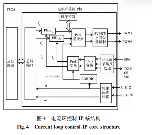
To achieve high-precision control of a single-axis motor, a single-axis motor control module was designed using a hardware-software co-design approach. The current vector control algorithm, characterized by high real-time performance and relatively singular algorithms, along with signal acquisition and processing algorithms, are implemented by a current loop control IP core designed with pure hardware logic. The highly flexible speed loop algorithm is implemented in software within an embedded soft core. The single-axis motor control module includes the following sub-modules: a current loop control IP core module, used to implement the current loop vector control algorithm and signal acquisition and processing algorithms for the corresponding axis, feeding back calculated position and speed information to the slave processor for closed-loop control. The slave processor first reads data from the on-chip shared memory to complete inter-core communication with the master processor; second, it receives speed information fed back from the current loop control IP core within the same module, executes the speed loop algorithm for the corresponding axis, and outputs current commands based on the calculation results; it also includes software functions such as closed-loop parameter configuration and various external interfaces. On-chip RAM is used to store the slave processor's program and provide its operating space.
To achieve independent and synchronous driving of multiple motors, the single-axis motor control module was expanded into multiple channels, and a multi-processor system-on-chip architecture was designed, with several modules added to enhance on-chip functionality. Data communication between multiple processors is achieved using a communication method that combines a MUTEX core with on-chip shared memory between the master and slave processors. A MUTEX core is added to enable mutual exclusive access to on-chip shared memory resources by multiple processors; on-chip shared RAM is added for data interaction and storage during communication between multiple processors.
The multi-processor system-on-chip also includes the following modules: a host PC communication module, which connects to the host PC, receives its commands and transmits them to the master processor, and simultaneously sends the real-time status of the controller to the host PC; a master processor, which processes host PC commands, dispatches tasks, and controls slave processors and other modules to complete tasks; an EPCS controller, which interfaces with external serial memory to configure FPGA data by transferring code from the serial memory; and an on-chip RAM module, which stores the master processor's program and provides its operating space.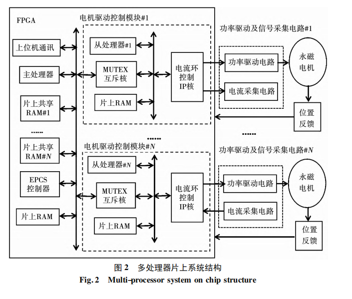 The multi-processor system-on-chip is designed within a single FPGA chip. The FPGA connects to the drive board via external interfaces to acquire position, speed, and current-related signals for processing and calculation, and outputs PWM signals for motor control. Each motor control module corresponds to a power drive and signal acquisition circuit, enabling interference-free, parallel driving. The power drive and signal acquisition circuit are integrated on a single drive board, consisting of three parts: the power drive circuit, the current signal acquisition circuit, and the position/speed feedback circuit.
4 Construction of a Two-Channel Experimental System
To verify the feasibility and effectiveness of the MPSoC-based multi-axis servo control solution, the existing single-axis motor control module was expanded into two channels, and a two-channel experimental system was built within a single FPGA chip for subsequent experimental validation.
The development platform used Cyclone V 5CEBA4F23C7N as the main control chip, containing 49K logic resources. Altera development software (Quartus II) provided the design environment and libraries, including the NIOS II soft core, Avalon bus, and customizable IP cores, for designing the multi-processor system-on-chip architecture. The two-channel experimental system utilized 32% of the FPGA's internal logic resources, specifically 5,476 adaptive logic elements. The FPGA clock frequency was 50 MHz, the current loop control frequency was 100 kHz, and the speed loop control frequency was 25 kHz.
This not only enables multi-axis motor drive control, host PC communication, and other functions but also enhances the integration level of the control platform. Systematically planning hardware and software functions ensures a reasonable allocation of functional modules across both hardware and software, thereby improving system flexibility and facilitating hardware and software design, ultimately reducing the design cycle.