STM32 + FPGA-Based Design and Implementation of a Marine Power Station Controller
In recent years, with the rapid development of semiconductor technology, microcontrollers (MCUs) based on ARM architecture and Field-Programmable Gate Arrays (FPGAs) have been widely applied in industrial field control due to their excellent performance, comprehensive functionality, stable supply, and lower costs [1]. Their application in marine engine room automation is also continuously deepening, showing broad application prospects.
Previous marine power station controllers typically centered around PLC devices, requiring corresponding basic modules such as power transducers, synchronization and paralleling modules, and digital input/output modules. Therefore, previous single generator set control units were built upon PLC-centric marine power station controllers. Such power station control systems had extremely complex networking and required significant installation space, greatly limiting their application prospects in modern vessels, especially in all-electric propulsion vessels with huge grid capacities [2].
To adapt to the development of modern vessel power station control systems, there is an urgent need for a power station controller that can perform all functions of previous marine power station controllers within a single module. The combination of modern embedded processors, especially ARM-architecture MCUs and programmable logic devices like FPGAs, can make this a reality.
1 ARM + FPGA Architecture Design
1.1 Functional Requirements of Marine Power Station Controller
Marine power station controllers require diverse types of control function interfaces, including digital interfaces, analog interfaces for basic control and safety protection of the prime mover and generator, and interconnection interfaces with other equipment within the marine power station system. Figure 1 shows the main interface signals of a single traditional diesel generator.
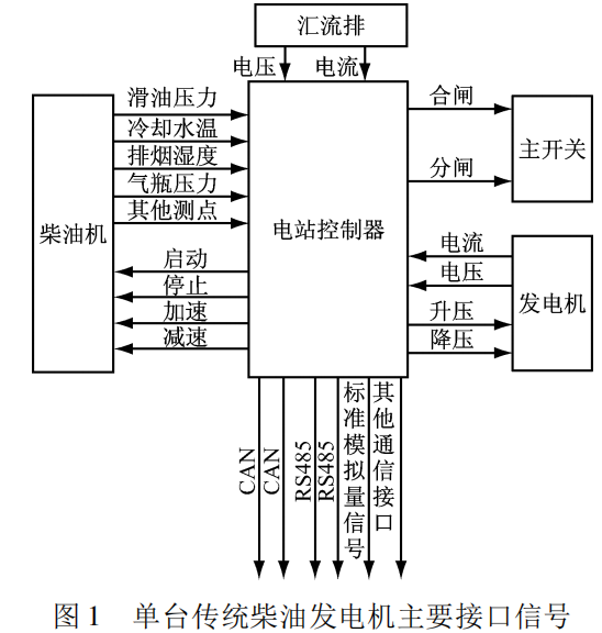
As shown in Figure 1, the functional interfaces required by the power station controller mainly include analog (AC and DC) interfaces, digital (digital input/output) interfaces, and communication bus (RS485, CAN, etc.) interfaces.
1.2 ARM + FPGA Architecture Selection
To meet the functional interface requirements of the power station controller, an ARM + FPGA architecture was selected as the basic architecture for the single-module power station controller.
The STM32F437 is an MCU based on a high-performance ARM Cortex-M4 32-bit RISC core. It integrates an FPU, Adaptive Real-Time (ART) Accelerator, MPU, 225 DMIPS / 1.25 DMIPS / MHz (Dhrystone 2.1), 256 + 4KB SRAM, a 32-bit data bus, and DSP instructions. With up to 2 MB of Flash memory and an operating frequency of up to 180 MHz, it is primarily used in industrial control fields and can meet the requirements for the core CPU's computing power and peripherals in a power station controller.
FPGAs are a further development based on programmable devices such as PAL, GAL, and CPLD, offering unparalleled advantages in logic control and timing control compared to other types of controllers. The power station controller needs to process a large number of logic signals, and critical safety protection logic cannot tolerate any errors. The FPGA's operating system, independent of the MCU, and its reliable logic processing capabilities make it the optimal choice for the power station controller's logic processing unit [3].
The EP2C5Q208C8 is an Altera Cyclone II series FPGA, featuring 4,608 LEs (with 119,808 bits of on-chip RAM), 13 18x18 hardware multipliers, 2 high-performance PLLs, and 142 user-defined I/Os. In terms of the number of logic gates and processing speed, it can fully meet the functional requirements of the power station controller.
2 Controller Hardware Design
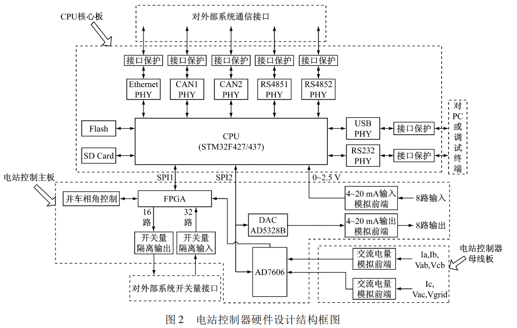
The hardware of the power station controller is designed based on the controller's interface resource requirements, capable of meeting the interface needs of most power station systems for single-unit controllers, and reserves some expandable interfaces for future industry development. The hardware design block diagram is shown in Figure 2.
2.1 Analog Acquisition Hardware Design
The analog quantities that the power station controller needs to process include AC power acquisition and DC power input acquisition.
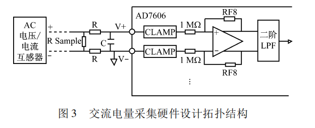
- For AC power acquisition, the AD7606 serves as the main acquisition component, connected to the MCU via an SPI bus. Designed and manufactured by ADI, the AD7606 integrates a 16-bit, 200 kSPS AD converter, enabling synchronous sampling of 6 AC signals. The AD7606's analog front-end features clamp protection, input buffers, and second-order anti-aliasing analog filters, ensuring the conditioning accuracy of AC signals. The hardware design topology for AC power acquisition based on AD7606 is shown in Figure 3.
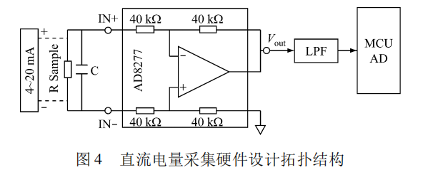
- The DC power acquisition section primarily acquires standard 4-20 mA current loop signals. Its analog front-end uses a differential input structure, which effectively reduces common-mode interference and improves acquisition accuracy. Back-end sampling is performed by the MCU's integrated AD converter, with a sampling accuracy of 12 bits. Leveraging the STM32F437's integrated AD converter's support for various sampling modes, digital filters are added to the MCU algorithm to further improve the acquisition accuracy of DC power. The hardware design topology for DC power acquisition is shown in Figure 4.
3 Controller Software Design
The power station controller software can be divided into an application layer, an application interface layer, and a driver layer. This layered software design allows developers to focus on a single layer of the overall structure to complete their tasks, thereby significantly improving development efficiency. Simultaneously, by reducing dependencies between layers, the software can be iteratively updated layer by layer, which further facilitates logic reuse between layers. Figure 7 shows the power station controller software design block diagram.
Figure 7 Power Station Controller Software Design Block Diagram
Key algorithms in the power station controller software design mainly include the core control algorithm, AC power measurement algorithm, and quasi-synchronous paralleling algorithm.
3.1 Power Station Controller Core Control Algorithm Design
The application layer primarily implements the core control algorithm of the power station controller, with its main functions including:
-
Automatic startup, operation, and shutdown of generator sets according to load requirements;
-
Automatic synchronization and paralleling of generators with the grid busbar;
-
Automatic constant grid voltage and frequency;
-
Automatic distribution and transfer of active and reactive load between parallel-running units;
-
Automatic shedding or connection of secondary loads based on power station load conditions;
-
Overload control;
-
Self-alarming and automatic protection for faults, and automatic engagement of corresponding healthy units and disengagement of faulty units according to a predefined procedure.
Each functional module of the power station controller's core control algorithm is embedded within the MCU. Configuration interfaces are also provided to enable and disable functional modules and configure their parameters. In practical applications, the operating modes of different functional modules can be flexibly configured for various vessel network configurations.
3.2 AC Power Measurement Algorithm Design
In a power station controller, AC power measurement is the most fundamental function and a prerequisite for ensuring the stability and reliability of other functions. The power station controller calculates AC power parameters, including voltage and current RMS values, active power, reactive power, power factor, and frequency, by acquiring 3-phase voltage and 3-phase current signals [4].