Industrial Touch Panel PC for Energy Storage Power EMS
The Energy Storage Energy Management System (EMS) offers comprehensive energy storage monitoring and management functions, covering detailed information on energy storage system equipment (PCS, BMS, electricity meters, fire protection, air conditioning, etc.). It achieves data acquisition, data processing, data storage, data query and analysis, visualized monitoring, alarm management, statistical reports, and other functions. For advanced applications, it supports energy dispatch, providing control functions such as scheduled curves, peak shaving and valley filling, demand control, and backup power. The system performs real-time monitoring and historical data analysis of battery pack performance, and based on the analysis results, it employs an intelligent allocation strategy for charge and discharge control of the battery packs, optimizing battery performance and extending battery life.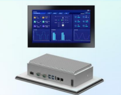 The system supports the Windows operating system, and the database uses SQL Server. This system can be used for both integrated energy storage cabinets and energy storage containers, serving as a software system platform specifically designed for energy storage equipment management.
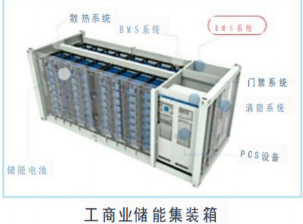
(1) Data Acquisition
Collect and display common information from each battery group of the Battery Management System (BMS), including total voltage, current, average temperature, SOC, SOH, charge/discharge current and power limits, single cell voltage, single cell temperature, equalization status of each cell, fault and alarm information, historical charge/discharge electricity, historical charge/discharge energy, capacity, chargeable amount, dischargeable amount, and charge/discharge cycles;
Collect and display relevant parameters of the PCS system, including: DC side voltage/current/power, three-phase active power, reactive power, three-phase voltage, three-phase current, power factor, frequency, operating status, alarm and fault information, as well as daily input power, daily output power, cumulative input power, and cumulative output power;
Collect various status variables of the energy storage system, including main circuit status (switches, emergency trip signals, protection action signals, abnormal signals).
(2) Data Processing
Real-time data display and processing functions;
Collect power quality data from smart meters, PCS systems, and measurement and control devices for statistical analysis and display; the energy management system can perform rationality checks and limit alarms on collected data.
(3) Data Storage
Store collected data in the accompanying database, with data granularity achieving hierarchical storage, and overall energy storage system information stored at a minute level.
(4) System Control
Receive and execute start/stop commands and power dispatch commands from the upper-level system to the energy storage system. The energy management system can control system operation, including power on/off, and dispatch power, voltage, and current commands defined by the inverter communication protocol, clearly outlining the step-by-step command process and current status to prevent misoperation.
(5) Curve Reports
Statistics on the energy storage system's operational status and power consumption, monthly power usage statistics for users, display of historical data, and data and report download functions.
(6) Alarm Function
Collect and display event log information and alarm information (including historical information) for the entire system. When analog quantities collected by the system exceed limits, digital quantities change state, or network communication self-diagnosis fails, the energy management system will automatically pop up an alarm window to notify the operator of the situation. This window remains on top of the screen until the operator handles it.
(7) Permission Management
The energy management system provides permission management, allowing different permissions to browse or download pages (data, tables, graphics, information) within different ranges. In a multi-layered energy storage system architecture, the upper-level energy management system displays the interface for the overall energy storage system, while the internal local energy management system only displays the interface for its specific internal energy storage system. In a single-layered energy storage system architecture, only a local energy management system exists.
(8) System Management:
The energy management system can monitor the primary electrical wiring of the energy storage system, generate a primary wiring diagram interface, and ensure key switches are visible and controllable.
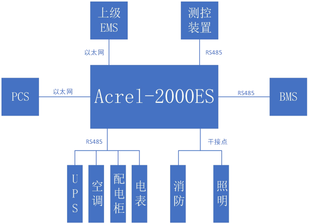
The energy management system can monitor the network operating status of the entire energy storage system (all control units and servers), display the overall system architecture topology diagram and basic information, and provide corresponding indications on the system topology diagram when anomalies occur.
The energy management system can monitor the operating status of each control unit in the entire energy storage system, and display them on the system topology diagram when anomalies occur.
(9) Other Functions:
Features for detecting and controlling UPS.
Features for reset and clear.