ARM+FPGA+AI-based Smart Ship Condition Monitoring System (Part 1) Overall Design
This article provides an in-depth analysis of the system requirements, specifications, and overall design for ship engine room monitoring equipment.
First, by thoroughly analyzing the system's functions and design characteristics, the design goals and requirements are clearly defined. Second, based on these needs and requirements, hardware and software system design solutions are proposed to achieve precise, reliable, and efficient performance. This in-depth exposition of the system's overall design provides a solid foundation for subsequent detailed design and implementation.
2.1 Device Functional Requirements Analysis
The overall objective of this project is to develop a complete set of ship engine room monitoring equipment for collecting various information about the ship's own equipment and its surrounding environment, performing data monitoring, transmission, and recording, thereby gaining a comprehensive understanding of the ship's condition and equipment operational status.
Based on the actual project requirements, the design of the ship engine room monitoring equipment must be highly reliable, fully incorporating existing mature reliability design technologies to ensure stability and safety during monitoring tasks. Concurrently, given the limited space and strict weight restrictions in the engine room, the development of the equipment must not only guarantee performance but also strictly control its size and mass to meet practical needs. To enhance the versatility of the equipment, resource allocation must be carefully considered to meet the demands of various monitoring tasks. In terms of performance, high-performance processors are utilized to ensure efficient data processing and analysis. Furthermore, an embedded system that is easy for secondary development is required to provide a convenient path for future upgrades and customization. Specific functional requirements are as follows:
(1) Multi-channel vibration and temperature signal detection capabilities. Ships are subjected to various vibrations and impacts during navigation, which can affect their structure and equipment. According to the "Guidelines for Inspection of Smart Engine Rooms of Ships" proposed by China Classification Society, parameters such as temperature, vibration, pressure, and flow can be used to monitor the operating conditions of engines and other equipment in the ship's engine room. Among these, vibration and temperature signals are the primary parameters for most equipment. By collecting such data and comparing it with normal operating conditions, the equipment's operational status can be assessed. This monitoring is crucial for preventing structural fatigue, diagnosing mechanical failures, and enhancing ship safety. Through real-time monitoring, ship maintenance personnel can take timely measures to avoid potential faults.
(2) Multi-channel analog voltage and current monitoring capabilities. Ship engine room monitoring often involves parameters such as flow and liquid level to monitor the status of various equipment. Some sensors used to collect these parameters output analog voltage and current. Therefore, an AD module for collecting analog voltage and current needs to be designed to convert these analog signals into digital signals for real-time monitoring, analysis, and recording by the system.
(3) Communication capabilities with multi-channel RS-232, RS-485, and CAN interfaces. The ship's engine room involves a large number of devices and subsystems, which may use different communication protocols. RS485, RS232, and CAN communication interfaces provide flexible data exchange methods, capable of connecting various devices such as sensors, engine control systems, navigation systems, and liquid level alarm systems. Through these interfaces, the monitoring equipment can exchange data, monitor, and control these devices, ensuring the ship's normal operation.
(4) Output excitation function. Implements digital switch functionality to control certain devices.
(5) Data storage and network communication functions. The monitoring equipment collects a large amount of data, requiring high-capacity storage. Additionally, this monitoring equipment needs to exchange data and enable remote monitoring with external systems. By providing dual Ethernet redundancy, the system can support high-speed data transmission and remote access, facilitating connection with the main control console, ship management systems, and more.
2.2 Device Performance Index Requirements
(1) Hardware Computing Platform: ① CPU: Minimum clock speed 1GHz; ② RAM: DDR4 (4GB); ③ Embedded Operating System: Linux;
(2) Interface and Acquisition Unit:
① Vibration signal interfaces: ≥16 channels;
② Analog voltage inputs: ≥8 channels, ±10V;
③ Analog current inputs: ≥8 channels, 420mA;
④ Temperature signal interfaces: ≥2 channels, measurement error -0.5℃+0.5℃;
⑤ RS232: ≥4 channels, strong anti-interference capability, communication parameters configurable via software;
⑥ RS485: ≥8 channels, strong anti-interference capability, communication parameters configurable via software;
⑦ CAN bus: ≥4 channels, strong anti-interference capability, uses FIFO for data transmission and reception, depth no less than 1024Bytes, polling read method, baud rate and other communication parameters configurable;
⑧ Gigabit Ethernet interfaces: ≥2 channels;
⑨ USB interfaces: ≥2 channels;
⑩ Digital switch status outputs: ≥6 channels;
(3) Data Management Unit: ① Data storage unit: At least 2TB, using solid-state drive;
(4) Power Supply: ① Supply voltage: Rated voltage 24V; ② Supply power: ≤80W;
(5) Environmental Adaptability: ① Operating temperature: -20℃~+55℃; ② Storage temperature: -55℃~+70℃; ③ Operating humidity: ≤95% (+30℃).
2.3 Device System Solution Design
The ship engine room monitoring equipment is primarily used for collecting various signals from ship equipment, communicating with certain devices or systems, and features data storage and high-speed transmission capabilities. This equipment mainly includes a main control platform, vibration, temperature, analog voltage and current signal acquisition modules, and communication modules such as RS232, CAN, and RS485.
Firstly, the selection of the main controller serves as the design basis for the monitoring equipment and is an important reference for the overall equipment layout planning. Given the limited space and strict weight restrictions in the engine room, the main control platform should be as lightweight, compact, and highly integrated as possible. The equipment requirements include multi-channel analog signal acquisition and communication via multi-channel RS232, RS485 standard UART, and CAN bus communication protocols. Traditional microprocessors have limited serial port and CAN port resources, and their processing speed is slower. Furthermore, future research may require the addition of other types of channels. Therefore, in scenarios involving the acquisition and processing of large amounts of data, a combination of FPGA+CPU is chosen for the design of this system, leveraging the advantages of FPGA's parallel processing in data acquisition and the CPU's strengths in task control and management to complete the design of the ship engine room monitoring equipment.
For the combination of CPU and FPGA, a comprehensive analysis suggests the main control chip selection schemes for ship engine room monitoring equipment are generally as follows: ARM+FPGA, DSP+FPGA, PowerPC+FPGA, ZYNQ, etc. Since the CPU's primary task is task scheduling, among the above options, DSP is more suitable for signal processing and less suitable for running Linux systems, so it was initially excluded. For the other three options, based on the requirements for high performance, miniaturization, and light volume, this design selects the ZYNQ series FPGA. This chip integrates an ARM processor and an FPGA chip internally. Within the chip, they are referred to as the Processing System (PS) side and the Programmable Logic (PL) side, respectively. They are connected via the AXI protocol, offering advantages such as high performance, low latency, and high bandwidth. This integrated approach not only reduces the physical complexity of the system and simplifies system design but also enables developers to design systems using a hardware-software co-processing method, maximizing the advantages of the ARM processor's time-sharing task processing and the FPGA's parallel processing and abundant logic resources Error! Reference source not found.。
Regarding the AXI protocol used within ZYNQ, communication primarily employs a 'handshake' mechanism between master and slave devices. Specifically, both sides use VALID and READY signals to control data transmission. The timing diagram for its transmission protocol is shown in Figure 2-1.
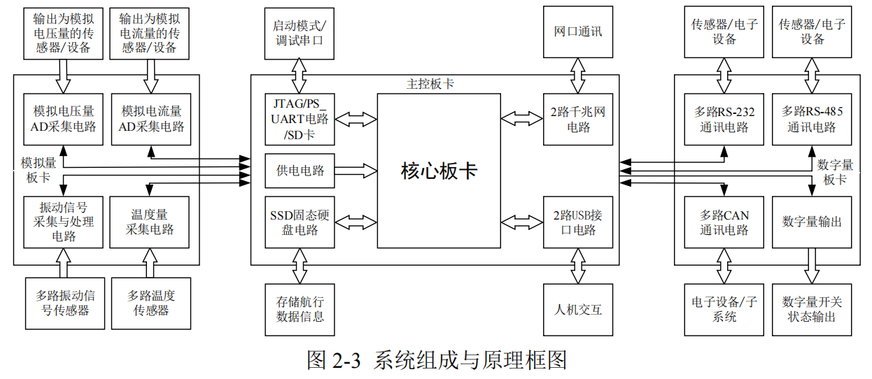
The overall workflow involves connecting analog and digital boards to lower-level devices, acquiring collected signal data and device communication data, caching and processing this data through the core board, and then communicating data with the ship's main control console via the designed dual-redundant Ethernet bus. The main design contents of each board are as follows:
(1) Analog Board: An indispensable component of the ship engine room monitoring equipment, performing critical functions. First, the vibration signal acquisition and processing circuit is responsible for real-time monitoring of vibration conditions in various key parts of the ship's engine room, monitoring the vibration status of mechanical components. Through collected vibration data, the system can analyze and evaluate the operational status of mechanical equipment in real-time, promptly detecting abnormal vibrations and predicting potential failures. Second, the analog voltage AD acquisition module is used to collect analog voltage signals output by sensors, supporting power stability monitoring and electrical parameter analysis. Third, the analog current AD acquisition circuit is responsible for measuring analog current signals output by motors, sensors, etc., helping to monitor equipment operating status and current load conditions in real-time. Finally, the temperature acquisition circuit monitors the temperature of key parts of the ship's engine room, providing temperature data for engines, motors, etc., to achieve temperature control and performance optimization. These functions provide the necessary data foundation for the ship monitoring system, helping to ensure the normal operation of ship systems, detect potential faults in advance, and take appropriate measures, thereby guaranteeing the safe and efficient operation of the ship and its equipment.
(2) Digital Board: Plays a crucial role in the monitoring system, offering multiple functions. First