Design and Implementation of a Domestic Secure Intelligent Interactive Terminal for EV Charging Piles Based on RK3568+AI, Supporting Complex Interactive Functions and Real-time Data Processing
To meet the demands of multi-party secure collaborative computing, ensure data confidentiality and integrity, and prevent data leakage and tampering, this article designs a secure intelligent interactive terminal suitable for EV charging piles (stations) based on the Rockchip RK3568 chip, adopting a method that combines a domestic operating system with a domestic processor. The terminal supports various complex interactive functions and real-time data processing requirements, which can enhance system stability and security, reduce international reliance, and provide a secure and user-friendly interactive environment at the charging pile (station) side [1-2].
1 Embedded Processor RK3568
The RK3568 is a mid-to-high-end, high-performance, low-power quad-core application processor chip. This processor features a quad-core CPU based on the Cortex-A55 architecture, a Mali-G52 GPU, and an NPU accelerator, capable of providing high computing performance and image processing capabilities to meet the demands of complex application scenarios. Manufactured using a 28 nm process, it has relatively low power consumption, allowing for extended operating time even in high-performance mode. The processor offers rich external interfaces, making hardware expansion straightforward. Furthermore, it features a product-oriented design for future hardware expansion and re-development [3].
2 Secure Intelligent Interactive Terminal Development Platform
Based on the terminal's R&D requirements, this article designs a core board based on the RK3568 processor, paired with domestic DDR4, eMMC, and PMIC chips. The designed core board features the following resources: 6 USB outputs, 3 SATA, 2 PCIe, 2 Camera, 2 MIPI_DSI, 4 video interfaces, 2 Ethernet interfaces, 2 SDIO, 4 SPI, 5 I2C, 10 UART, 3 CAN, 4 audio interfaces, 16 PWM, and 1 FSPI. The block diagram of the core board's hardware resources is shown in Figure 1:

3 Circuit Design of Functional Modules for the Secure Intelligent Interactive Terminal
Based on the self-developed terminal core board, the circuit design for functional modules such as memory, power management, and security encryption modules in the terminal is as follows:
3.1 Terminal Power Management Circuit
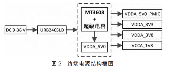
The power management circuit supplies power to the secure intelligent interactive terminal, ensuring its safe and stable operation. Key considerations in designing the power management circuit include operating voltage, current, power, size, cost, ripple, and electromagnetic compatibility. The terminal's power structure is shown in Figure 2. The terminal power module has a voltage input range of DC 9–36 V. A DCDC power module URB2405LD outputs 5 V, which is combined with a boost converter chip and supercapacitors to form a backup power supply. Subsequently, LDO and DCDC circuits generate VDDA_5V0_PMIC, VDDA_3V3, VDDA_3V8, and VCCA_1V8, respectively [4].
As shown in Figure 3, 5V_DC is the main power supply, 5V_SC is the power supply boosted by the supercapacitor, and 5V_OUT is the output power supply. The 5V_DC output from the DCDC power module is connected to a backup power supply system with seamless, no-dropout switching. This system includes a supercapacitor module (comprising two 50 F/2.7 V supercapacitor cells connected in series), a supercapacitor charge and discharge circuit, and a supercapacitor protection circuit (consisting of one XC61CC2702MR protection chip, one N-MOS transistor, and one discharge resistor). Following the supercapacitor module is a DCDC boost circuit, whose main component is the MT3608 switching power supply control chip. Through a combination of components such as inductor L1, capacitor C4, and Schottky diode D2, it achieves voltage conversion where the input voltage is lower than the output voltage, ensuring the supercapacitor's output voltage remains stable near the system's required voltage. The boosted outputs from the main power supply and the supercapacitor enter a dual-channel, no-dropout seamless switching circuit, finally outputting VDDA_5V0 to power the system.
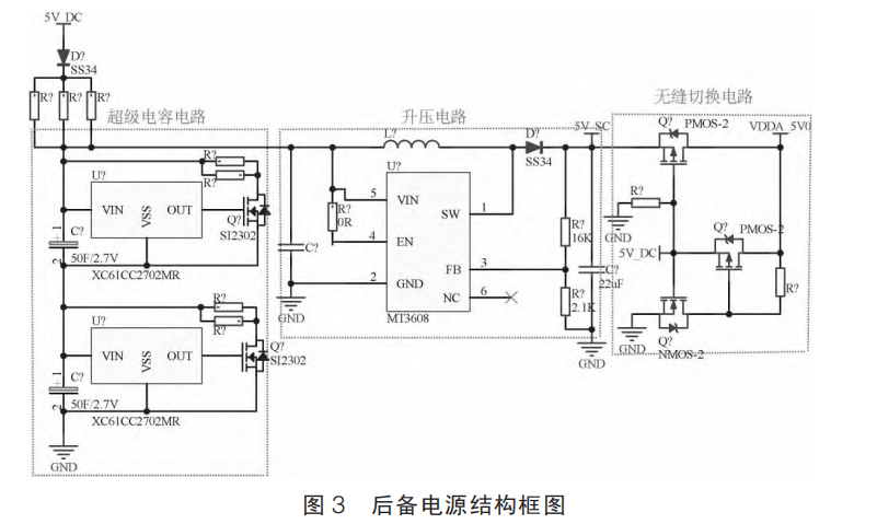
When the external power supply fails, the built-in supercapacitor module, through boost, regulation, and switching circuits, achieves seamless, no-dropout switching, ensuring the terminal operates normally for at least 10 seconds. Concurrently, a metering module based on the OpenHarmony system real-time monitors information such as terminal input voltage, supercapacitor voltage, and output voltage. This monitoring information is sent to the platform in real-time using communication methods like Ethernet and 4G [5].
The core board's PMIC circuit has an input voltage of 2.7–5.5 V and integrates five configurable synchronous buck converters, nine LDO regulators, two switches, one RTC, and one battery fuel gauge. All input terminals feature a soft-start function to reduce current impact on the front-end power supply. Compensation circuits are integrated within the chip, eliminating the need for external resistors, capacitors, and other additional components. A total of 13 voltage module outputs are designed. The main power supply is 5 V input, with four DC/DC channels generating VDD_LOGIC, VDD_GPU, VCC_DDR, and VDD_NPU, respectively. Nine LDO channels generate VDDA0V9_IMAGE, VDDA_0V9, VDDA0V9_PMU, VCCIO_ACODEC, VCCIO_SD, VCC3V3_PMU, VCCA_1V8, VCCA1V8_PMU, and VCCA1V8_IMAGE, respectively.
The RK809 fuel gauge system accurately measures battery power based on the charge and discharge characteristic curves of different batteries. It provides battery power information to the system's main chip via the I2C interface. It dynamically adjusts the output voltage of each DC-DC converter according to the processor's operating status. This significantly reduces inrush current during startup, enhances the terminal's operational reliability, and maximizes system efficiency.
5 Conclusion
With the massive influx of heterogeneous data from charging facilities, the security and reliability of information transmission have become particularly crucial. Therefore, charging pile (station) side terminals need to strengthen information security on existing foundations to cope with application scenarios such as large-scale data access and vehicle-to-grid (V2G) interaction. The terminal designed in this article will ensure efficient, secure, and reliable data transmission and sharing required for the collaborative operation of charging facilities and the power grid. This not only facilitates the large-scale application of charging facilities but also supports and promotes the coordinated optimization, flexible operation, and digital transformation of power systems. It has broad application prospects in fields such as intelligent transportation and smart grids.