ZYNQ-based Strain and Temperature Synchronous Acquisition System for Engine and Gas Turbine Testing (Part 2): Acquisition System Software and Hardware Design
Acquisition System Hardware Design
3.1 Control Board Circuit Design
3.1.1 Main Control Chip Selection
When selecting the main control chip for the acquisition system, the following factors should be comprehensively considered to ensure it meets system requirements:
(1) Processing Capability and Performance: Based on task requirements, the main control chip needs to possess sufficient computing resources to handle the processing load and computational demands of the data acquisition system. To meet these needs, factors such as the number and type of processor cores, clock speed, and instruction set must be fully considered during selection. Given potential future system upgrade and expansion requirements, choosing a high-performance processor can prevent performance bottlenecks when adding new features or processing more data.
(2) Interface Compatibility: The main control chip needs to support various physical and logical interfaces required for connection and communication, ensuring that the chip can properly exchange data with other system components (such as sensors, storage modules, and communication modules).
(3) Software Support and Ecosystem: Selecting a main control chip model that supports multiple development tools and operating systems can effectively simplify the development process and enhance system scalability and flexibility.
In this system, communication with various module circuits needs to be established, and some components require logical control. Due to the operating environment, wireless communication with the host computer is also necessary. Considering the above factors, the Xilinx ZYNQ-7000 series XC7Z020CLG400-2 chip was ultimately selected as the main control chip.
3.1.2 Clock Circuit Design
Two independent base clocks are designed on the control board for the PL (Programmable Logic) and PS (Processing System) sections of the ZYNQ chip, respectively. The PL section's clock is a 50MHz active crystal oscillator, with its schematic shown in Figure 3-1. The crystal oscillator output for the PL section, PL_GCLK, is connected to the PL's Global Clock (MRCC), specifically pin U18 IO_L12P_T1_MRCC. This provides a clock to the PL section's user logic. When the logic requires clocks of other frequencies, frequency multiplication or division can be achieved through corresponding IP cores.
ZYNQ Application Design
The main task of the application in this system is to coordinate the entire data flow, including starting and stopping data acquisition, processing received data, and sending data to the host computer. The application needs to interact effectively with hardware and process data at all stages. This requires the application to meet the following demands to ensure efficient system operation and accurate data transmission.
(1) Using the POLL function for blocking I/O: The POLL function is used to implement blocking I/O. In this case, the application suspends the corresponding thread when data is not yet ready, reducing wasted CPU resources.
(2) Using IOCTL control provided by the driver: IOCTL is primarily used to control the start and end of acquisition and to read data.
(3) Using sockets to send data: The application uses sockets to establish network connections and then sends the processed data to the host computer.
In this system, the data acquisition module transmits data to the data processing module via a Wi-Fi module. The Linux operating system provides sockets for network programming. A socket domain may have multiple different communication methods, each with its own characteristics. In the network domain, we need to pay attention to the characteristics of the underlying network, as well as two different communication mechanisms: Stream Sockets and Datagram Sockets:
(1) Stream Sockets: Use the TCP protocol, providing reliable, connection-oriented communication that guarantees data order and integrity. However, due to their reliability, stream sockets may sacrifice some real-time performance in certain situations.
(2) Datagram Sockets: Use the UDP protocol, providing connectionless communication services where data transmission does not guarantee reliability, order, or data integrity. They are suitable for applications with higher real-time requirements.
As a strain/temperature synchronous acquisition system, this system has high real-time requirements. Furthermore, the acquisition system will need to operate in harsh environments, such as rotating environments, in the future. When network conditions are poor due to environmental factors, the UDP protocol offers a simple data transmission mechanism that does not require maintaining complex connection states, data sequence numbers, and acknowledgment mechanisms like the TCP protocol. This makes it more suitable for harsh environments. Therefore, the system uses datagram sockets to match the actual needs of the acquisition system.
4.7 Host Computer Design
Based on existing research group achievements, the host computer software was developed using the Microsoft Visual Studio integrated development environment and the .NET framework. The system communicates with the host computer via a Wi-Fi module. The host computer includes modules for parameter configuration, data acquisition, data playback, and data export. Its operating modes are divided into measurement mode and playback mode, with the workflow shown in Figure 4-10.
In measurement mode, the hardware system first requires parameter configuration, including selecting communication protocols, transmission rates, and performing system self-checks. After modifying and saving the parameters, the configuration is sent to the hardware system of the rotor component. Once configured successfully, the system can receive real-time acquired data. Data is transmitted to the host computer via the Wi-Fi module, parsed, and then displayed in real-time on the software interface. When the host computer issues a stop acquisition command, the host computer software closes the reception thread, saves the acquired raw data, and updates the data file. This mode allows for effective monitoring of the system's operating status and signal changes.
In playback mode, historical data saved on the computer can be viewed. The host computer software reads the selected data file and redraws the data curves according to the time sequence, helping users review and analyze historical data, and study signal characteristics and trends.
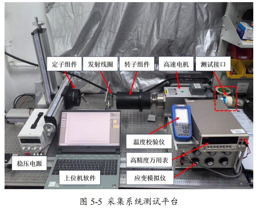
A high-precision benchtop multimeter, the KEITHLEY 2002 digital multimeter from Keithley Instruments, is used. It features high precision, high stability, and high resolution, and is employed in testing to accurately measure voltages and currents at various nodes.
The conST313 multi-function temperature calibrator is selected to simulate standard voltages and signals generated by different types of standard thermocouples at various temperatures. During testing, the temperature values acquired by the system need to be compared with the set values of the conST313 to evaluate the error of the temperature signal.
The XL2106-6 standard strain simulator is chosen as the test platform to generate strain signals. This device can produce strains up to ±111111με with an accuracy of 0.05% in the 0-5kHz range. The standard strain simulator can simulate full-bridge and half-bridge type bridges with a bridge arm resistance of 120Ω. Using this device allows for precise simulation of strain signals, providing an accurate and reliable basis for strain measurement.
A DC power supply, model MS-3610DS, provides voltage to the acquisition system.