FPGA-based 3U Chassis Analog High-Speed Sampling ADI Board, Applied in Rail Transit/Power Energy Storage, etc.
FPGA-Based 3U Chassis Analog High-Speed Sampling ADI Board for Rail Transit and Power Energy Storage Applications
Precision motor control in demanding industrial environments — rail transit drives, power energy storage inverters, grid-tied converters — hinges on fast, accurate feedback of two physical quantities: rotor speed and phase current. This post introduces a 3U chassis analog high-speed sampling board (ADI) built around a Xilinx Spartan-6 FPGA, designed specifically to close that feedback loop with the signal fidelity and isolation margins that industrial deployments require.
What the Board Does
The ADI board serves as the analog front-end for motor closed-loop control systems. It simultaneously captures:
- Motor speed via frequency detection on up to six channels, accepting signals with amplitudes up to 15 V. These channels are well-suited to resolver-derived square waves, Hall-effect sensor outputs, or encoder differential signals that have been conditioned to single-ended form.
- Phase current via eight analog acquisition channels. The default channel configuration ships with asymmetric ranges: ICAP0 is calibrated for DC currents from 0 to 63 mA (a low-side shunt or reference measurement path), while ICAP1 through ICAP7 cover a bipolar ±450 mA range suited to shunt-based phase current sensing on the motor drive. Importantly, the board includes fine-tuning circuitry that allows the sampling range to be adjusted without redesigning the PCB — a practical provision when the board must be adapted to different motor ratings or transducer output scales.
Beyond acquisition, the board provides eight isolated ±24 V power rails for driving external sensors or signal conditioning stages, removing the need for a separate power daughter card in many system configurations.
FPGA: Xilinx Spartan-6 XC6SLX25
The processing core is the XC6SLX25-3FGG484I, a Spartan-6 device in a 484-ball BGA package. The XC6SLX25 offers approximately 24,000 logic cells, 52 DSP48A1 slices, and 936 Kb of block RAM — more than sufficient to implement high-speed PWM capture for frequency measurement, pipeline the ADC data stream, and manage the SPI interface concurrently in fabric. The -3 speed grade and I temperature suffix confirm this is the industrial-grade variant, rated for operation across the extended temperature range that the board's −25 °C to 70 °C specification demands.
Using an FPGA rather than a fixed-function DSP here is deliberate: frequency counting logic, oversampling filters, and communication framing can all be updated in firmware as system requirements evolve, without hardware respins.
Backplane Communication: High-Speed SPI
The board communicates with the host processor or system controller through a high-speed SPI bus on the backplane connector. SPI is a natural fit for this data path — it is deterministic, has negligible protocol overhead, and is straightforward to implement in FPGA fabric with tight timing closure. In a 3U chassis, the backplane SPI link connects the ADI board to a main control card (often an ARM- or DSP-based CPU board), which runs the closed-loop control algorithm using the frequency and current samples delivered over this link.
The choice of backplane-side SPI rather than a front-panel connector keeps signal routing short and shielded within the chassis, which matters at the sampling rates needed for real-time current control.
Power Supply Architecture
The board accepts four supply rails from the chassis backplane:
| Rail | Typical Use |
|---|---|
| DC 5 V | Digital logic, FPGA I/O banks |
| DC 3.3 V | FPGA core / configuration logic |
| DC ±15 V | Analog signal conditioning op-amps |
| DC ±24 V | External sensor power (re-distributed via the 8 output channels) |
The presence of ±15 V rails is a strong indicator that the analog front-end uses precision op-amp stages — these supply voltages provide the headroom needed to maintain linearity at the top of each current measurement range without clipping. The ±24 V output channels are buffered from the input rail and distributed to external current transducers or signal conditioners attached to the motor drive.
Physical and Environmental Specifications
| Parameter | Value |
|---|---|
| Dimensions | 220 mm × 100 mm × 1.6 mm |
| Weight | 0.145 kg |
| Operating Temperature | −25 °C to 70 °C |
| Form Factor | 3U chassis card |
The 220 × 100 mm footprint is consistent with a standard 3U Eurocard form factor, designed to slide into a card cage with a backplane connector. At 145 grams, the board is light enough that vibration-induced connector stress is minimal — relevant in rail and industrial settings where chassis vibration is a constant environmental factor.
The −25 °C lower bound covers cold-start conditions in outdoor rail equipment, while the 70 °C upper limit accounts for elevated chassis temperatures in sealed enclosures without forced air.
Target Applications
The combination of fast frequency detection, multi-channel bipolar current acquisition, and a rugged industrial temperature range makes this board directly applicable to:
- Rail transit traction drives — monitoring axle motor speed and phase currents for torque control loops
- Power energy storage systems — measuring charge/discharge currents in battery inverter stages where high accuracy and isolation are critical
- Grid-connected converters — phase current feedback for PFC or grid-tie control
- Industrial servo drives — any application where resolver or Hall speed signals and shunt current signals must be digitized at high speed for a real-time control loop
Functional Block Diagram
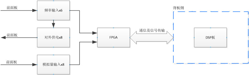
The block diagram illustrates how the six frequency detection channels and eight analog current channels feed into the FPGA fabric, which aggregates the data and presents it to the host controller via the backplane SPI interface. The ±24 V output distribution and the multi-rail power input are also shown, confirming the board's role as a self-contained analog front-end module within the 3U chassis system.