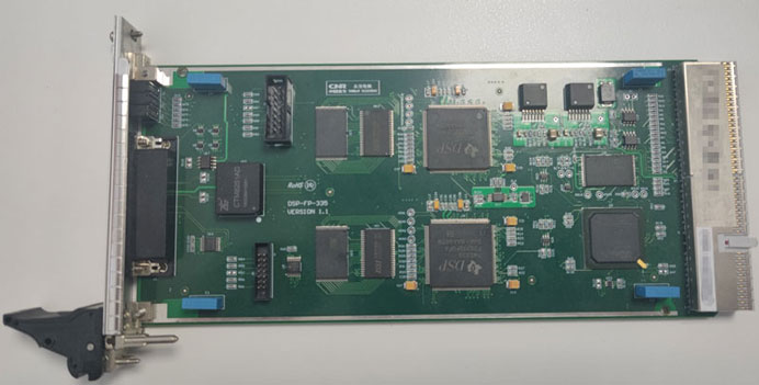
CPCI Motor Control Board (DSP) for Rail Transit 3U Chassis, Primarily Running Control Algorithms for Precise Motion Control of Traction Motors
Rail transit traction systems demand extremely tight control over motor torque, speed, and rotor position across wide temperature ranges and electrically noisy environments. This post covers a 3U CPCI motor control board built around a dual-TMS320F28335 DSP architecture, designed to run real-time control algorithms for precise motion control of AC traction motors. The board is a production-grade embedded computing card that slots into a CompactPCI chassis and handles everything from current sampling and frequency detection to CAN-based communication with supervisory controllers.
Application Context: Traction Motor Control in Rail Transit
In electric rail vehicles — metro trains, light rail, and locomotives — the traction inverter converts DC bus power into variable-frequency, variable-voltage AC to drive the traction motor. The motor controller sitting between the supervisory vehicle control unit (VCU) and the inverter gate drivers is responsible for implementing the core control algorithms: typically field-oriented control (FOC) or direct torque control (DTC). These algorithms are computationally intensive and time-critical. A single control loop iteration must complete within tens of microseconds to maintain stable operation at high motor speeds, which is why dedicated DSP hardware — rather than a general-purpose CPU — is the standard choice.
The 3U CompactPCI form factor is well-suited to this environment. CPCI provides a mechanically robust, hot-swappable backplane with defined vibration and shock specifications, which aligns with railway EN 50155 deployment requirements. The compact 220 mm × 100 mm × 1.6 mm PCB profile fits within the 3U height envelope while leaving room for the dense analog front-end circuitry needed for current and frequency sensing.
Processor Architecture: Dual TMS320F28335
The board carries two TMS320F28335 DSPs from Texas Instruments. The F28335 is a 32-bit fixed/floating-point DSP from TI's C2000 Piccolo/Delfino line, running at up to 150 MHz with a Harvard bus architecture optimized for control applications. Its on-chip peripherals — including PWM generators with dead-band control, quadrature encoder pulse (QEP) interfaces, and 12-bit ADCs — are purpose-built for motor drive work.
Using two F28335 devices in parallel is a common partitioning strategy for high-performance traction controllers. A typical split assigns one DSP to the inner current control loop (fast, microsecond-level) and the second DSP to the outer speed/torque loop, supervisory logic, and communication handling. This separation prevents communication latency from polluting the deterministic timing of the PWM generation and current regulation loops.
FPGA Co-Processor: Xilinx Spartan-6 XC6SLX25
The Xilinx XC6SLX25-2FG484I is a Spartan-6 series FPGA in the 484-ball BGA package. With approximately 24,051 logic cells and 52 DSP48A1 slices, the Spartan-6 is well-suited for glue logic, high-speed I/O management, and pre-processing tasks that would otherwise consume DSP cycles. In traction controller designs, the FPGA typically handles:
- PWM output arbitration and interlock logic — enforcing dead-time insertion and cross-conduction protection at the hardware level, independent of DSP software state.
- Encoder signal processing — decoding incremental or resolver signals at frequencies that exceed the DSP's interrupt handling bandwidth.
- CPCI bus interface — bridging the DSP data buses to the CompactPCI backplane protocol.
- Frequency detection pre-processing — counting and timestamping edges on the six frequency input channels before the DSP reads the results.
The FPGA is backed by 16 MB of PROM for configuration storage, ensuring reliable bitstream loading at power-on without relying on external host intervention.
Memory Subsystem: Shared SRAM and FLASH
The board implements a shared memory architecture between the DSPs and the FPGA:
- SRAM: 4 Gb × 2 — Two banks of high-speed static RAM shared across the DSP and FPGA fabric. Shared SRAM enables low-latency data exchange between the FPGA pre-processor and the DSP control loops without going through a serial peripheral interface. In a dual-DSP design, each DSP typically claims one SRAM bank as its primary workspace, with the FPGA able to read/write both banks for DMA-style data transfers.
- FLASH: 8 Gb × 2 — Non-volatile storage shared by DSP and FPGA, used for firmware images, parameter tables, and fault logs. The dual-bank arrangement supports A/B firmware update schemes, allowing a new firmware image to be written to the inactive bank and activated on next boot — a safety-critical requirement for field-upgradeable rail equipment.
Communication Interfaces
Front Panel (Field-Side)
| Interface | Count | Notes |
|---|---|---|
| Isolated CAN | 2 | Galvanically isolated; suitable for noisy traction bus environments |
| Non-isolated CAN | 1 | Typically used for intra-chassis communication |
| RS-232 | 2 | Debug console or legacy supervisory link |
CAN isolation is important in rail applications where ground potential differences between subsystems can reach tens of volts. The two isolated CAN ports likely connect to the vehicle's main control network (e.g., MVB or proprietary CAN backbone), while the non-isolated channel handles shorter-distance links within the same cabinet.
Backplane (System-Side)
The CPCI bus backplane interface connects the board to the 3U chassis and the system controller. CompactPCI uses a 32-bit/33 MHz PCI bus mapped to the Eurocard connector, providing adequate bandwidth for parameter updates, telemetry upload, and firmware download while the DSPs handle real-time control independently.
Analog Front-End
Frequency Detection — 6 Channels (0–15 V Amplitude)
Six frequency measurement channels accept signals in the 0–15 V amplitude range. In traction applications these inputs typically connect to speed sensors, resolver excitation feedback, or grid frequency references. The FPGA handles edge detection and period measurement at hardware speed, with results buffered into shared SRAM for the DSP to consume at its control loop rate.
Analog Current Acquisition — 8 Channels
Current sensing is the most measurement-critical function in a motor controller. The board provides eight channels with the following default scaling:
- ICAP0: DC 0–63 mA — suited for low-current auxiliary measurements (e.g., field current in a separately-excited machine, or sensor excitation monitoring).
- ICAP1–7: ±450 mA — bipolar range for AC phase current measurement via Hall-effect sensors or current transformers with resistive burden.
Critically, the datasheet notes that sampling ranges can be modified via fine-tuning circuitry. This is typically implemented as a resistor-programmable gain stage ahead of the ADC input, allowing the board to be reconfigured for different motor ratings or sensor output levels without firmware changes — an important flexibility feature for a platform card that may be deployed across multiple vehicle programs.
External Power Output — 8 Channels ±24 V
Eight ±24 V power output channels allow the board to directly supply sensor excitation, relay coils, or actuator drivers without requiring a separate power distribution board. This reduces cabling complexity and consolidates fault protection within the motor controller card itself.
Environmental and Mechanical Specifications
| Parameter | Value |
|---|---|
| Power Supply | DC 5 V, DC 3.3 V |
| Dimensions | 220 mm × 100 mm × 1.6 mm |
| Weight | 0.160 kg |
| Operating Temperature | −25 °C to +70 °C |
The −25 °C to +70 °C operating range covers typical rail depot and trackside conditions in temperate climates. The 1.6 mm PCB thickness and 160 g weight are consistent with a densely populated 3U card optimized for vibration resistance in rolling stock.
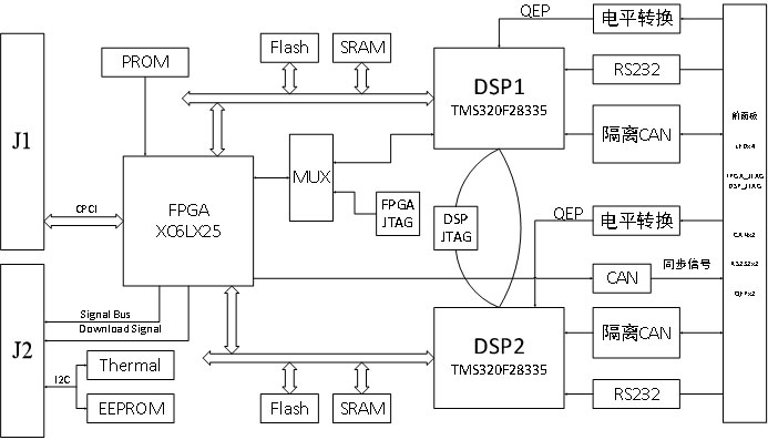
Functional Block Diagram
Summary
This CPCI motor control board represents a well-considered architecture for rail traction applications: dual F28335 DSPs divide the real-time control workload, a Spartan-6 FPGA handles hardware-speed I/O and bus interfacing, and a shared SRAM/FLASH memory subsystem keeps inter-processor data exchange latency low. The isolated CAN interfaces, configurable current-sensing ranges, and onboard ±24 V power outputs make the card self-contained enough for deployment as a standalone traction controller node within a 3U CPCI chassis. The wide operating temperature range and compact form factor align with EN 50155 railway electronics requirements, making this board a practical platform for precision motor control in metro, light rail, and locomotive drive systems.