FPGA-based Rail Transit CPCI Fiber Optic Board (6U)
FPGA-Based Rail Transit CPCI Fiber Optic Board (6U): LVDS-to-Optical Signal Conversion for High-Speed Backplane Communication
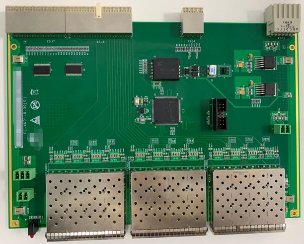
Industrial rail transit systems demand communication links that are immune to electromagnetic interference, capable of operating across wide temperature ranges, and reliable enough to meet the rigorous uptime requirements of passenger rail infrastructure. This 6U CPCI fiber optic board addresses those requirements by converting LVDS (Low-Voltage Differential Signaling) electrical signals to optical signals, bridging high-speed on-board data buses with the outside world through twelve SFP fiber ports.
What This Board Does and Why It Matters
LVDS is the signaling standard of choice inside many industrial computing backplanes: it is fast, low-power, and differentially encoded to reject common-mode noise. The problem is that LVDS is inherently a short-distance copper interface — it is not suited to running across a railcar, let alone between cars or to wayside equipment. Fiber optics solve this cleanly: glass or polymer fiber carries light rather than current, making it immune to the ground loops, voltage spikes, and broadband EMI that are endemic to traction power environments.
This board sits in a 6U CompactPCI (CPCI) slot and acts as the electro-optical gateway between the main control board (which communicates via the CPCI backplane) and up to twelve external fiber links. The conversion is handled in real time, preserving the high-speed characteristics of the original LVDS link while extending the physical reach of the communication channel to fiber-optic distances.
Core Logic: Xilinx CoolRunner-II CPLD
The signal conversion and routing logic is implemented in a Xilinx XC2C256-7TQ144I CPLD — a member of the CoolRunner-II family. With 256 macrocells in a 144-pin TQ package and a speed grade of -7, this device provides deterministic, low-latency combinational and registered logic without the configuration-load delay of an FPGA. CoolRunner-II parts are known for their ultra-low standby current (in the microamp range), which suits battery-backed or power-sensitive rail applications where the board may need to remain partially powered during system sleep states.
The -I suffix on the part number denotes the industrial temperature variant, which is rated for operation down to −40 °C — well below the board's own rated floor of −25 °C, ensuring the logic device is never the thermal weak link in the design.
Communication Interfaces
Backplane Side (CPCI Connector)
| Interface | Count | Purpose |
|---|---|---|
| RS-485 | ×1 | Low-speed serial control / management |
| I²C | ×1 | Configuration bus, SFP module management |
The RS-485 port on the backplane side provides a robust half-duplex serial link for supervisory control, status polling, or firmware updates from the main control board. RS-485 is a natural fit here: it is multi-drop capable, tolerates long cable runs (up to 1200 m at lower data rates), and its differential encoding gives it strong noise immunity consistent with the rest of the board's design philosophy.
The I²C bus is most likely used for SFP transceiver management. Every SFP module exposes a standardised I²C address space (the SFF-8472 MSA) that allows the host to read optical power levels, temperature, transmitter bias current, and vendor identification. Routing this management bus through the backplane I²C interface allows the main control board to monitor the health of all twelve optical links without any dedicated management processor on the fiber board itself.
Front Panel Side (SFP Cages)
| Interface | Count | Typical Reach |
|---|---|---|
| SFP | ×12 | Depends on transceiver: 100 m (multimode) to 10+ km (single-mode) |
Twelve SFP (Small Form-factor Pluggable) cages on the front panel give the board a high degree of flexibility. Because SFP is a pluggable standard, the system integrator can choose transceivers suited to the specific installation — short-range 850 nm multimode for inter-rack links within a control cabinet, or 1310 nm single-mode for longer runs to wayside equipment. Twelve ports is a substantial channel count for a single slot, enabling dense aggregation of fiber links from multiple subsystems (traction control, door control, CCTV, passenger information, etc.) into one compact CPCI card.
Mechanical and Environmental Specifications
| Parameter | Value |
|---|---|
| Form Factor | 6U CPCI |
| PCB Dimensions | 160 mm × 233.5 mm × 1.6 mm |
| Weight | 0.145 kg |
| Power Supply | DC 5 V |
| Operating Temperature | −25 °C to +70 °C |
The 160 × 233.5 mm footprint is consistent with the IEC 60297 / IEEE 1101.1 6U Eurocard standard used by CompactPCI. At 1.6 mm PCB thickness this is a standard stackup, accommodating the SFP cage height and CPLD package within the slot pitch of a standard 6U CPCI chassis.
The operating temperature window of −25 °C to +70 °C covers the range a rail transit system would realistically encounter: arctic winter station environments on the cold end, and a sun-baked equipment cabinet or under-floor enclosure in summer on the hot end. The 5 V single-supply design simplifies power distribution from the CPCI backplane, which mandates ±5 V and ±12 V rails; using only 5 V keeps power consumption low and eliminates the need for local DC-DC conversion.
Functional Architecture
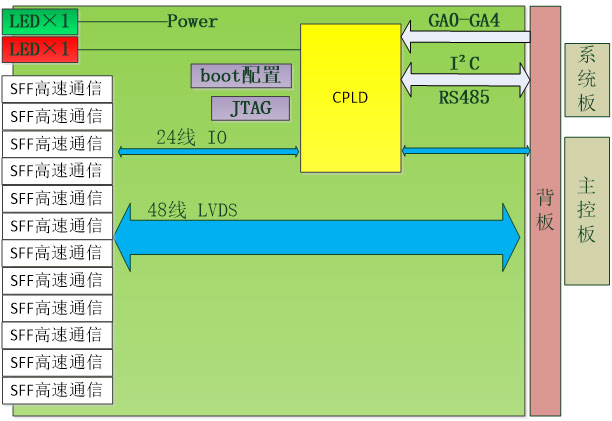
The functional block diagram illustrates the signal path from CPCI backplane to fiber: LVDS signals from the backplane are received, processed through the XC2C256 CPLD, and serialised out to the SFP transceivers on the front panel. The reverse path — incoming optical data from the SFP modules — is deserialised and driven back onto the LVDS backplane bus. The RS-485 and I²C interfaces branch off as separate control-plane channels, keeping management traffic isolated from the high-speed data path.
Typical Application in Rail Transit
In a rail transit TCMS (Train Control and Management System) architecture, this board would occupy a slot in a 6U CPCI chassis mounted in the train's central control cabinet. The main control board — typically a PowerPC or ARM-based single-board computer — communicates with this fiber board over the CPCI backplane. The twelve SFP ports then fan out to distributed I/O nodes, HMI displays, network switches, or inter-car communication links running through the train's fiber backbone. The result is a centralised, high-density optical aggregation point that keeps the main control board free of fiber connectors while delivering the electromagnetic robustness that rail certification standards require.