FPGA-Based Audio and Video Monitor and Video Interface Capture Device Applications
FPGA technology has become a cornerstone of professional broadcast and industrial video processing, offering the deterministic, low-latency pipeline performance that software-only solutions struggle to match. This article introduces two FPGA-based product categories — a professional audio/video monitor with real-time analysis tools, and a flexible video interface capture device — covering their key capabilities and the engineering use cases they address.
FPGA-Based Professional Video Monitor
Modern broadcast and cinematography workflows demand more than simply displaying a picture. Colorists, camera operators, and post-production engineers need objective, real-time signal analysis to make confident exposure and color grading decisions. An FPGA implementation is well-suited to this role: the parallel processing fabric can simultaneously compute waveform data, build histogram bins, and render the display pipeline without the frame-drop risk inherent in a CPU-based approach.
The monitor described here accepts one HDMI input and one SDI input, which covers the two dominant interfaces in professional video production. HDMI is ubiquitous for on-set monitors and consumer-grade cameras, while SDI (Serial Digital Interface) is the broadcast industry standard for its robust, locking connector and long cable runs. Outputting via one HDMI port at 1080P allows the processed signal — including all overlaid analysis data — to be passed downstream to a field monitor or recording device without disrupting the live signal chain.
Real-Time Signal Analysis Tools
The FPGA pipeline renders the following analysis overlays simultaneously, which is the key differentiation from software tools that typically process one view at a time:
- Waveform (luminance/RGB): Plots pixel intensity by horizontal position, giving the operator an immediate read on exposure and clipping across the frame. Separating the R, G, and B channels independently is essential for identifying color balance issues.
- Histogram: Aggregates the tonal distribution of the entire frame into a frequency chart, useful for confirming that highlights are not clipped and shadows retain detail.
- Vector scope: Displays the chrominance (hue and saturation) components of the signal on a polar plot, the standard tool for verifying skin tone reproduction and legal color gamut compliance.
Exposure and Focus Monitoring Overlays
The device supports five overlay tools commonly found on professional broadcast monitors:
- Focus peaking: Highlights high-frequency edge detail in a contrasting color, helping camera operators confirm critical focus without magnifying the frame.
- Zebra pattern: Superimposes a diagonal striping pattern over pixels that exceed a user-defined IRE threshold, providing a live, at-a-glance indicator of over-exposure.
- False color: Remaps the luminance range to a color gradient (typically from blue/green for underexposure through red/pink for clipping), giving a quick, whole-frame exposure map.
- Monochrome: Strips the chrominance signal and displays luminance only, which makes it easier to judge contrast ratios and spot focus issues without color distraction.
- Safe area / aspect ratio markers: Draws configurable frame lines for broadcast safe zones and common aspect ratio crops (e.g., 16:9, 2.39:1), ensuring composition is verified during production.
Color Science Features
3D LUT (Look-Up Table) support allows the monitor to apply a transformation cube to the incoming signal, enabling on-set log-to-display (e.g., S-Log, ARRI LogC) color conversion so that the operator views a graded image rather than a flat log signal. 3D LUTs describe a full color transform in three-dimensional RGB space and are the industry-standard format for communicating color intent between camera, set, and post-production.
Color temperature calibration allows the display itself to be calibrated against a known reference, ensuring that the analysis tools and rendered image are grounded in a consistent white point rather than drifting with temperature or aging.
Additional Capabilities
- Free zoom and real-time partial image display: The FPGA scaler can magnify any region of the frame and display it at full output resolution, useful for pixel-level focus or defect inspection.
- Audio level meters (VU/peak): Visual audio bars confirm that embedded audio in the HDMI/SDI stream is present and within acceptable levels.
- Image rotation and mirroring: Allows the monitor to be physically rotated or used with a reflected optical path (common in some rig configurations) without additional hardware adapters.
Audio and Video Interface Capture Device
Beyond monitoring, many production and broadcast infrastructure scenarios require capturing, converting, or routing video signals between interfaces. The capture devices described below address this with FPGA-accelerated signal processing.
Single-Channel HDMI Capture and Conversion
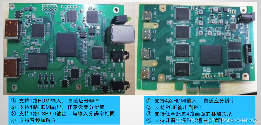
The single-channel variant accepts one HDMI input with auto-adaptive resolution detection, meaning the FPGA negotiates the incoming pixel clock and timing parameters automatically across a range of source resolutions (e.g., 720p, 1080p, 4K) without manual configuration.
- HDMI output with user-defined resolution: The output path runs through an FPGA scaler, allowing the signal to be up- or down-converted to a resolution independent of the source. This is practical for feeding displays or downstream recorders that require a fixed format.
- USB 3.0 output at native input resolution: A USB 3.0 interface (SuperSpeed, 5 Gbps) carries the raw capture data to a connected PC or embedded host. At 1080p60 with 8-bit color, the uncompressed bitrate is approximately 3 Gbps, well within USB 3.0 bandwidth, making real-time capture practical without compression artifacts.
- Audio embedding and de-embedding: The device can extract embedded audio from the HDMI stream (de-embedding) and insert audio into an outgoing HDMI signal (embedding), which is critical for workflows where audio and video are managed on separate paths before being recombined.
Four-Channel HDMI Capture with PCIe Output
The four-channel variant scales up the capture capability to handle multi-source environments such as multi-camera production, video wall control systems, or industrial machine vision arrays.
- Four HDMI inputs with auto-adaptive resolution: Each input independently negotiates its source timing, so mixed-resolution sources can feed the device simultaneously without a common sync requirement.
- PCIe output to PC: Rather than USB, this variant uses a PCIe interface, which provides significantly higher sustained bandwidth and lower latency — important when four simultaneous high-resolution streams must be transferred to the host without frame drops. PCIe Gen 2 x4, for example, offers approximately 16 Gbps of theoretical throughput.
- Configurable overlay of four input channels: The FPGA compositor allows each of the four inputs to be arranged, layered, and mixed in a user-defined layout, enabling quad-split views, picture-in-picture configurations, or custom multi-window arrangements.
- Windowing, roaming, scaling, and rotation per channel: Each source window can be independently positioned anywhere on the output canvas, resized, and rotated, giving the operator full compositional control without external switching hardware.
Summary
These FPGA-based products address two distinct but complementary needs in professional video infrastructure. The monitor targets on-set and broadcast QC workflows where simultaneous, real-time signal analysis and color-accurate display are non-negotiable. The capture devices target infrastructure and integration scenarios where flexible interface conversion, multi-channel aggregation, and high-bandwidth host transfer are the primary requirements. In both cases, the FPGA fabric provides the parallel processing headroom necessary to handle these tasks with frame-accurate determinism that CPU or GPU pipelines cannot easily replicate in latency-sensitive environments.