All-domestic VPX 3U CAN Communication Board, VPX 3U KIO Card, PCIe x1 Expansion Digital I/O Interface
Overview
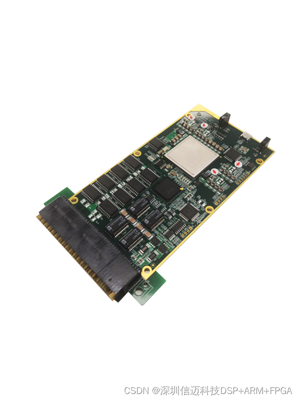
Industrial computing platforms increasingly demand compact, ruggedized expansion cards that can bridge modern PCIe-based compute boards with legacy fieldbus and discrete I/O ecosystems. This post covers two all-domestic (国产) VPX 3U expansion cards built around a PCIe x1 interface: a CAN communication board offering eight isolated CAN channels, and a KIO card providing 16-channel digital input plus 16-channel digital output with built-in monitoring. Both cards are designed to fit the VPX 3U form factor, making them suitable for embedded military, railway, and industrial control applications where ruggedness, slot density, and domestic-supply-chain compliance are mandatory.
VPX 3U CAN Communication Board
What It Does
The CAN communication board plugs into a PCIe x1 slot on a VPX backplane and exposes eight fully independent CAN 2.0 channels. Each channel is galvanically isolated, meaning a fault or ground-potential difference on the field side cannot propagate back to the host processor. This is essential in heavy industrial and vehicle environments where the CAN bus may run alongside high-voltage actuators, motors, or automotive power rails.
Key Electrical and Protocol Specifications
| Parameter | Value |
|---|---|
| Host interface | PCIe x1 |
| CAN channels | 8, fully independent |
| Isolation | Per-channel galvanic isolation |
| Interrupt routing | 1 dedicated interrupt per channel |
| Supported baud rates | 125 kbps, 250 kbps, 500 kbps, 1 Mbps |
| Termination resistors | Not fitted on-board (external or at bus endpoints) |
The choice to omit on-board termination resistors is deliberate and correct engineering practice for a multi-drop CAN bus: the CAN spec requires exactly two 120 Ω termination resistors placed at the physical ends of the bus. Placing them on an expansion card that sits somewhere in the middle of the cable run would violate this requirement and cause reflections. The termination should be placed at the far end of each CAN segment, typically at the sensor or actuator.
Interrupt-per-Channel Design
Assigning one hardware interrupt line to each CAN channel is a significant advantage over shared-interrupt designs. In a shared-interrupt model, the driver must poll all channels to determine which one fired, adding latency and CPU overhead. With per-channel interrupts, the host can handle a high-priority channel immediately without servicing lower-priority channels first. This matters in real-time control loops where CAN message latency directly affects control stability.
Baud Rate Configurability
The four standard baud rates — 125, 250, 500 kbps, and 1 Mbps — cover the vast majority of deployed CAN networks. 500 kbps is the de facto standard for automotive-derived industrial systems; 125 kbps is common in longer-run process automation networks where cable capacitance limits speed. The ability to set each channel independently means a single board can bridge multiple CAN segments operating at different speeds, a common requirement when integrating legacy subsystems with newer designs.
VPX 3U KIO Card — PCIe x1 Digital I/O Interface
What It Does
The KIO (Key I/O) card also rides a PCIe x1 host interface and provides 32 discrete I/O points arranged as 16 inputs and 16 outputs. A third 16-channel output bank with monitoring capability (described below) rounds out the feature set. This kind of card is the backbone of machine control, interlock logic, and status signaling in industrial applications.
Digital Input Specifications
| Parameter | Value |
|---|---|
| Input channels | 16 |
| Isolation type | Opto-coupler (photocoupler) |
| High-level threshold | 18 V |
| Low-level threshold | 6 V |
| Required drive current | ≥ 30 mA |
The opto-coupler isolation ensures that the PCIe host is protected from field-side transients, which in industrial settings can include inductive switching spikes well above 100 V. The 18 V / 6 V thresholds are intentionally wide: this input is designed to work with 24 VDC PLC I/O systems, where "high" nominally means 24 V (threshold at 18 V gives healthy noise margin) and "low" nominally means 0 V (threshold at 6 V rejects ground noise and leakage current from sinking inputs). The 30 mA minimum drive requirement is the LED forward current needed to reliably switch the opto-coupler; any 24 V PLC output rated at 0.5 A or more will comfortably satisfy this.
Digital Output Specifications
| Parameter | Value |
|---|---|
| Output channels | 16 standard + 16 with monitoring |
| High-level voltage | Power supply voltage (20 V – 32 V) |
| Low-level voltage | 0 V – 1 V |
| Single channel contact capacity | 1 A |
The output stage swings to the supply rail (20–32 V), making it directly compatible with 24 VDC solenoid valves, relay coils, indicator lamps, and similar actuators without any level-shifting circuitry. The 0–1 V low-level ceiling is tight enough to satisfy most PLC input low thresholds and to keep the voltage across a solenoid coil negligibly small when the output is de-energized, preventing partial actuation.
Output Monitoring
The 16-channel output monitoring feature deserves special attention. In safety-relevant applications, it is not enough to command an output — the system must also verify that the physical line actually drove high or low. Monitoring typically works by reading back the output pin state through a separate sense path (sometimes opto-isolated independently) and comparing it to the commanded state. A mismatch indicates a wiring fault, a blown fuse, a welded contact, or an open-circuit actuator — all conditions that would otherwise go undetected until a functional failure occurred in the field. This readback capability is often required by IEC 61508 SIL assessments and by railway functional safety standards such as EN 50128.

VPX 3U Form Factor and Domestic Supply Chain
Both cards conform to the VITA 46 VPX standard in the 3U height (100 mm). VPX's high-speed differential connector system makes it well suited to carry PCIe lanes between a compute blade and peripheral cards on a passive backplane, enabling the dense, shock-resistant packaging demanded by avionics and mobile military platforms. The "all-domestic" (全国产) designation indicates these cards are manufactured using components sourced within China's domestic supply chain — an increasingly important procurement requirement for government, defense, and critical-infrastructure projects in China. Pairing these I/O expansion cards with a Phytium-based compute blade (the Phytium FT series being China's leading domestic server-class ARM processor family) yields a fully domestic VPX subsystem that covers computation, CAN fieldbus, and discrete I/O without reliance on foreign semiconductor supply.
Typical Application Scenarios
- Vehicle control units: CAN channels interface with chassis ECUs, transmission controllers, and sensor nodes; digital outputs drive relay-controlled actuators; digital inputs read limit switches and door sensors.
- Railway trackside equipment: Multiple isolated CAN segments at mixed baud rates aggregate data from distributed sensor nodes; output monitoring provides the fault-detection evidence required by EN 50128 safety cases.
- Industrial machine control: 24 VDC I/O connects directly to PLC-style sensors and actuators, while the CAN interface links to drive inverters and smart field devices running CANopen or DeviceNet protocols.
- Ruggedized embedded systems: The VPX 3U mechanical envelope survives the shock, vibration, and wide temperature ranges encountered in mobile platforms, where desktop-class PCIe add-in cards would fail.