IPU Overview
- IPU Overview
(I) Architecture
First, let's look at the overall system architecture diagram of the i.MX 6Q to understand the IPU's position within the entire SoC system:
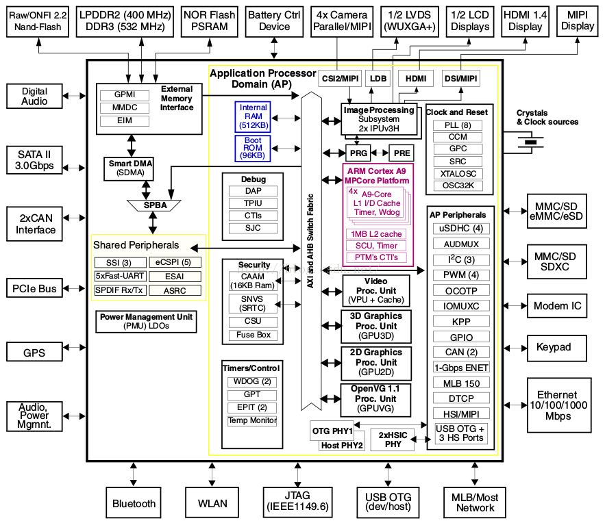 As can be seen, the entire IPU is connected to the AXI and AHB buses, allowing it to communicate with modules such as ARM, VPU, GPU, and RAM via these buses.
Additionally, each IPU has two camera interfaces, as shown below:
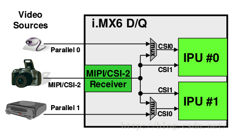
It controls LVDS screens via LDB, directly controls LCD screens, and can display content via HDMI or MIPI.
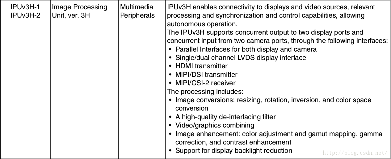
The function of the IPU is explained in the diagram below:
Alternatively, the diagram below provides a clearer representation:
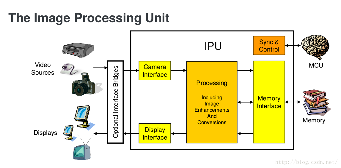 The above describes the overall architecture of the IPU. For BSP, we are more concerned with its driver hierarchical framework, as shown below:
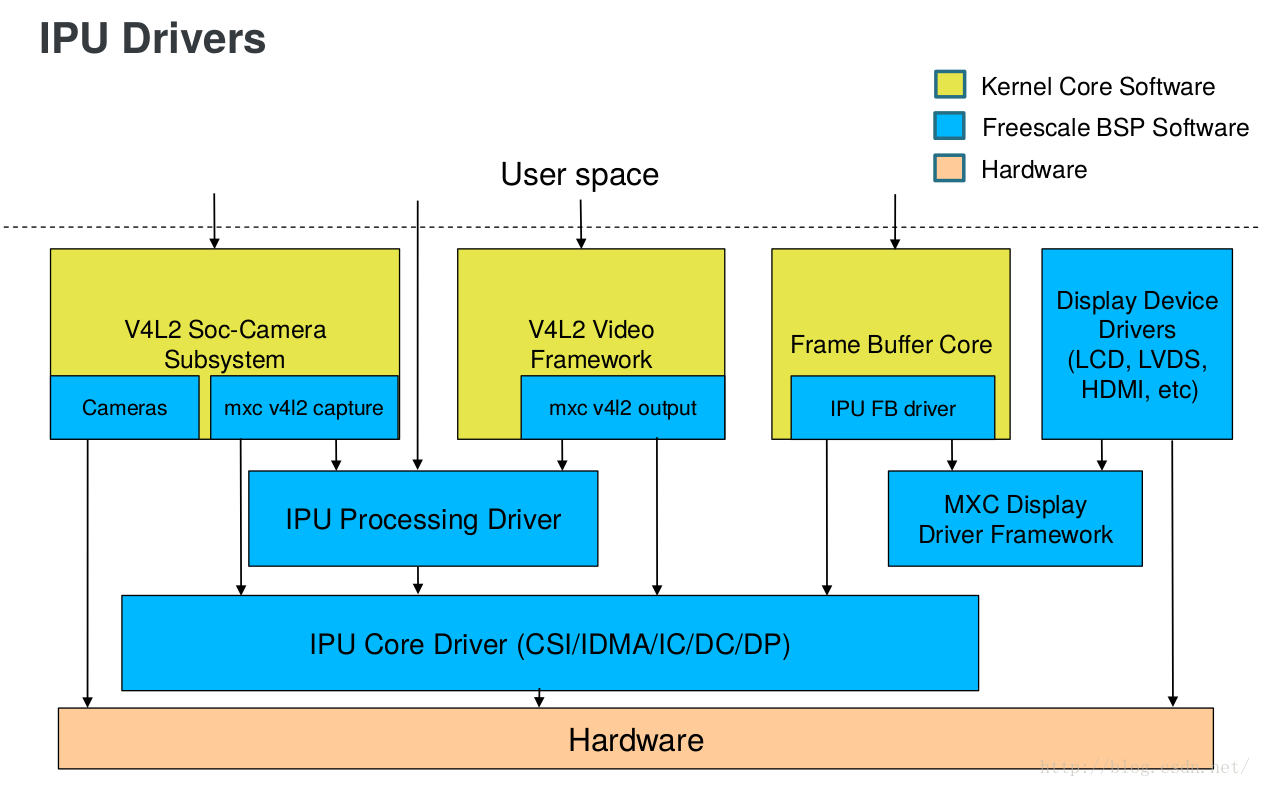
From this framework, it can be seen that a typical V4L2 subsystem communicates with hardware through the IPU.
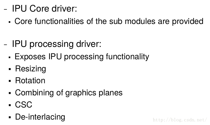
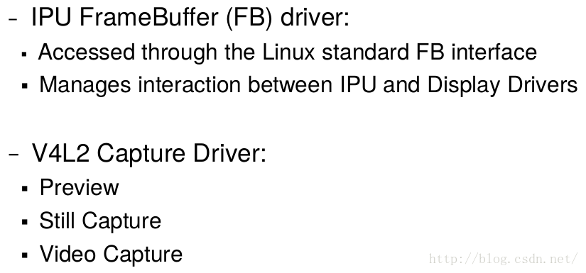
Functions of each module in the diagram:
(II) Codebase Structure Kernel Version: 3.14.52 Files are mainly located in: .../drivers/mxc/ipu3/ Description ipu_device.c Operations for IPU tasks, etc. (IPU core driver) ipu_common.c Core functions for the low-level layer ipu_capture.c Provides function operations for ipu_common.c ipu_disp.c IPU display ipu_ic.c Operations for IC ipu_param_mem.h Header file for CPMEM settings, operation functions .../drivers/mxc/mipi/ mxc_mipi_csi2.c Operations for MIPI cameras .../drivers/media/platform/mxc/ capture/mxc_v4l2_capture.c Provides open, ioctl, and other operation functions for applications capture/v4l2-int-device.c Subsystem module registration and other operation functions capture/ipu_prp_enc.c Pre-processing encoder driver functions capture/ipu_csi_enc.c CSI device driver operation functions capture/ipu_still.c Still image capture functions capture/ipu_prp_vf_adc.c Pre-processing view finder (asynchronous) driver capture/ipu_prp_vf_sdc.c Pre-processing view finder (synchronous foreground) driver capture/ipu_fg_overlay_adc.c Foreground/background overlay asynchronous driver capture/ipu_bg_overlay_sdb.c Background overlay synchronous driver capture/ov5640.c ov5640_mipi.c ov5640.c subsystem driver
(III) Analysis Steps This driver will be analyzed from the following points:
- Overview
- Master and slave matching process
- Analysis of mxc_v4l2_capture.c 3.1 Analysis of the probe function 3.2 Call process of vidioc_int_* class functions 3.3 Underlying execution flow of function calls in applications 3.4 Analysis of the mxc_v4l_open function 3.5 Detailed explanation of the cam_data structure 3.6 Analysis of the mxc_v4l_ioctl function 3.7 Detailed analysis of cases within the ioctl function 3.8 Detailed analysis of the poll function
- Analysis of ipu_common.c 4.0 Detailed explanation of ipu_soc, ipu_channel_t, and ipu_channel_params_t structures 4.1 Analysis of ipu_common.c --- Entry function and probe function analysis 4.2 Analysis of ipu_common.c --- Detailed analysis of the ipu_init_channel function 4.3 Analysis of ipu_common.c --- Detailed analysis of the ipu_init_channel_buffer function 4.4 Analysis of the ipu_param_mem.h header file 4.5 Detailed analysis of the ipu_request_irq function 4.6 Detailed analysis of the ipu_enable_channel function 4.7 Analysis of ipu_capture.c
- Example: Step-by-step analysis of the call process in the mxc_v4l2_capture.c application 5.1 Trace analysis of the mxc_v4l2_capture.c application 5.2 Buffer transfer process between application and driver
- Subsystem analysis 6.1 Detailed analysis of ipu_prp_enc.c 6.2 Detailed analysis of ipu_csi_enc.c 6.3 Detailed analysis of ipu_still.c 6.4 Detailed analysis of ipu_ic.c
- Analysis of ipu_device.c 7.1 Analysis of ipu_device.c (Part 1) --- Flow analysis 7.2 Analysis of ipu_device.c (Part 2) --- Specific function analysis
- Analysis of various modules 8.1 Sub-module analysis: IDMAC 8.2 Sub-module analysis: CSI 8.3 Sub-module analysis: SMFC 8.4 Sub-module analysis: IC 8.5 Sub-module analysis: VDIC 8.6 Sub-module analysis: CM
- DTS file analysis --- Taking OV5640 as an example, modifying the DTS file to make OV5640 use the second IPU
- Understanding ipu_init_channel, preparing for future channel additions
- Analysis of ov5640_mipi.c