ZYNQ-based Multi-Channel Encoder Acquisition and Interpolation Control System for Industrial Robots | High-Precision Real-Time Motion Control Solution
ZYNQ-based Multi-Channel Encoder Acquisition and Interpolation Control System for Industrial Robots | High-Precision Real-Time Motion Control Solution
📌 Article Summary: Industrial robots and multi-axis servo motion platforms demand extremely high performance for real-time encoder sampling, high synchronization, trajectory interpolation, and ultra-low latency control. Traditional microcontroller (MCU) and bare-metal ARM solutions suffer from low counting speed, poor multi-axis synchronization, interpolation calculation stutter, and inability to follow high-speed movements. This article leverages the ZYNQ heterogeneous architecture, utilizing the parallel hardware capabilities of FPGA to achieve high-speed quadrature decoding for multi-channel encoders. The ARM processor handles trajectory planning, S-curve acceleration/deceleration, and linear/circular interpolation, enabling industrial-grade multi-axis robot motion control. This approach resolves the pain points of traditional controllers, such as poor real-time performance, significant jitter, and low synchronization accuracy, making it directly applicable to four-axis/six-axis robots, servo motion platforms, and automated slide projects.
🔑 Keywords: ZYNQ, Robot Control, Multi-channel Encoder, Quadrature Decoding, Trajectory Interpolation, Motion Control, FPGA Real-time Decoding
I. Project Background and Industry Pain Points
Industrial robots and multi-axis servo platforms are typical multi-axis collaborative high-precision motion equipment, relying fundamentally on encoder feedback for closed-loop control. Motion control precision directly depends on encoder sampling frequency, multi-axis synchronization accuracy, and the real-time performance of interpolation calculations.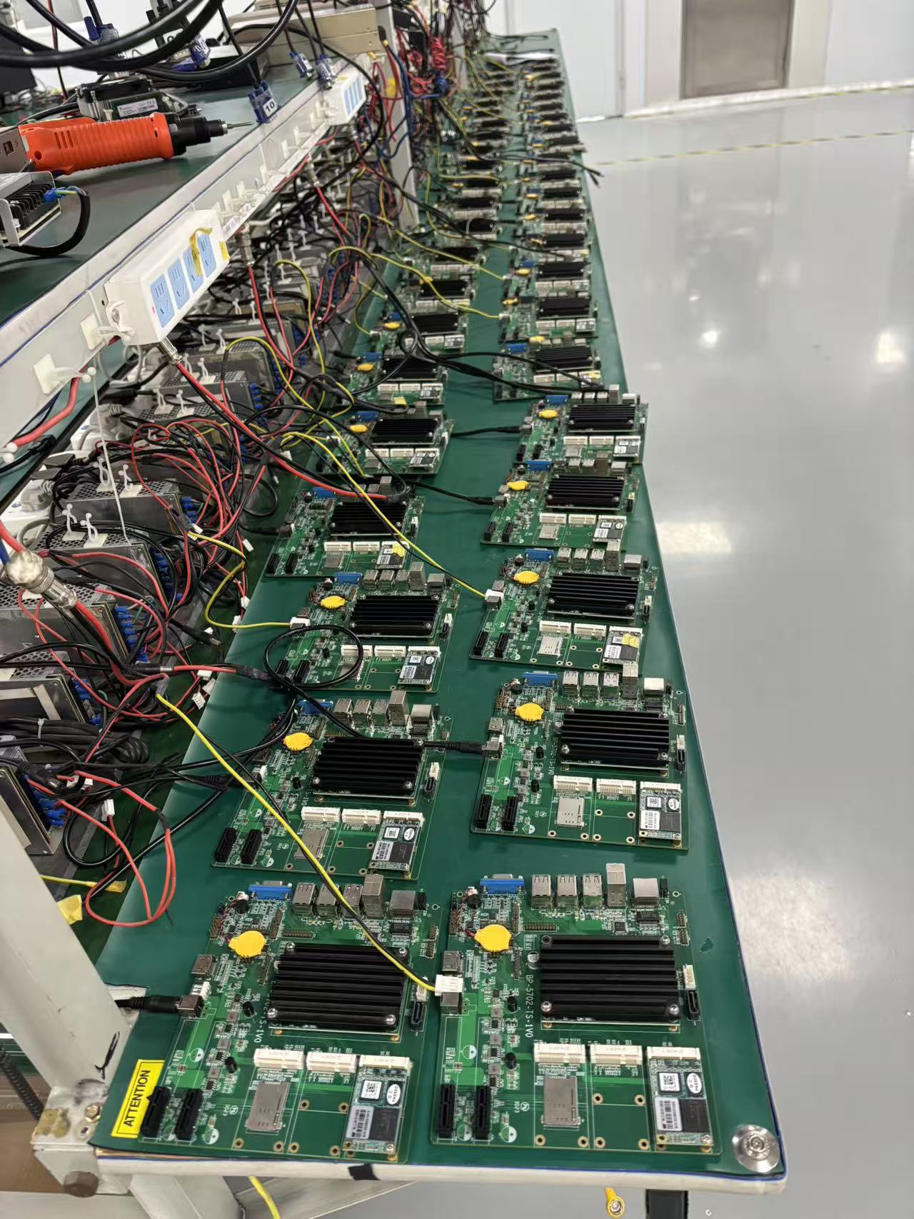
Current mainstream traditional control solutions on the market have significant shortcomings:
- STM32/Microcontroller Solutions: Low timer decoding frequency, prone to pulse loss when acquiring multiple encoders simultaneously, high latency with pure software interpolation, and severe jitter during high-speed motion.
- Standard Linux Industrial PC Solutions: Large system scheduling jitter, poor hard real-time performance, unable to meet microsecond-level closed-loop control requirements for servos.
- Commercial Motion Control Cards: Expensive, highly proprietary, difficult for secondary development, and cannot adapt to customized robotic equipment.
- Pure FPGA Solutions: Extremely high logic development difficulty, cumbersome trajectory planning and interpolation algorithm porting, and weak human-machine interaction and networking capabilities.
The ZYNQ FPGA+ARM heterogeneous architecture perfectly solves these problems: The FPGA hardware performs multi-channel encoder decoding, pulse counting, and high-speed I/O control in parallel, without system jitter. The ARM processor runs Linux to handle complex trajectory algorithms, parameter management, and host computer interaction, balancing real-time performance with flexibility. It is the optimal lightweight solution for small to medium-sized industrial robot controllers.
II. System Core Design Specifications
This robot motion control system is designed for industrial multi-axis linkage scenarios, with core parameters benchmarked against entry-level industrial motion controllers:
- Supported Channels: Up to 6 channels of servo encoder synchronous acquisition, suitable for six-axis industrial robots.
- Decoding Method: FPGA hardware AB-phase quadrature decoding, increasing sampling precision by 4 times.
- Real-time Performance: Encoder decoding and pulse counting are hardware-timed, with no software delay and nanosecond-level response.
- Motion Algorithms: Supports linear interpolation, circular interpolation, and S-curve acceleration/deceleration trajectory planning.
- Control Output: Multi-channel high-speed pulse/direction signal output, compatible with mainstream servo drives.
- Synchronization Accuracy: Multi-axis encoder sampling timing is fully synchronized, with no phase deviation.
- Expansion Capabilities: Supports Modbus/TCP communication, host computer trajectory download, and online parameter debugging.
III. Overall System Architecture Design
The system adopts the classic ZYNQ heterogeneous division of labor model, where the PL (Programmable Logic) side is responsible for hard real-time low-level acquisition and control, and the PS (Processing System) side handles complex algorithms and business interaction. This decouples hardware and software, with each performing its dedicated functions.
3.3.1 FPGA (PL Side) Core Functions
- Hardware filtering, debouncing, and quadrature decoding for 6 AB-phase encoder signals.
- Real-time position and velocity pulse counting, with hardware registers updated in real-time.
- Multi-channel PUL/DIR high-speed pulse output with precise timing control.
- AXI high-speed register mapping for ARM to read encoder data in real-time.
- Real-time interrupt detection for limit and home signals.
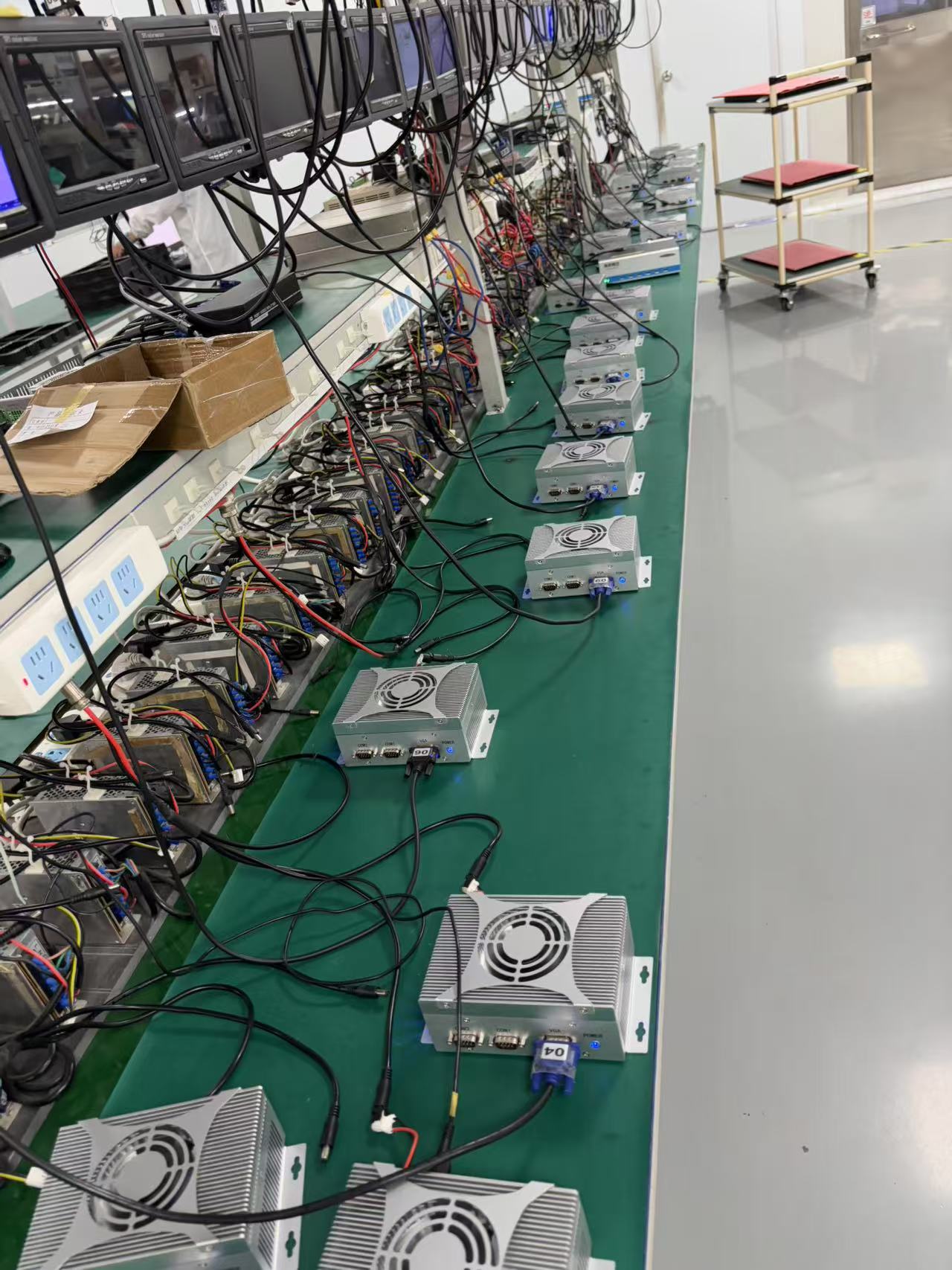
3.3.2 ARM (PS Side) Core Functions
- Reads real-time position and velocity data from the PL-side encoders.
- Implements S-curve acceleration/deceleration algorithms and linear/circular interpolation trajectory planning.
- Multi-axis position loop and velocity loop closed-loop calculations.
- Receives motion commands, trajectory points, and parameter configurations from the host computer.
- Provides motion status feedback, fault detection, and data upload.
3.3.3 Overall Data Flow
Servo Encoder Signals → FPGA Hardware Filtering + Quadrature Decoding → Position/Velocity Register Caching → AXI Bus Real-time Upload to ARM → Trajectory Interpolation + Closed-loop Calculation → FPGA Pulse Output Controls Servo Motor → Forms Closed-loop Motion Control
IV. FPGA Key Logic Design (Core Technology)
4.4.1 Encoder Signal Preprocessing
In industrial environments, long-distance encoder signal transmission can easily introduce high-frequency interference and jittering pulses, leading to position jumps and inaccurate positioning if counted directly. This design implements multi-stage hardware debouncing and filtering for each encoder signal on the FPGA. By sampling with a high-frequency clock, stable voltage levels are locked, and high-frequency interference pulses are filtered out, enhancing the system's anti-interference capability at the hardware level.
4.4.2 AB-Phase Quadrature Decoding Principle and Implementation
Standard 2x decoding has low precision and cannot meet the high-precision positioning requirements of robots. This system employs hardware quadrature decoding, detecting a total of four edges (rising and falling edges of both A and B phases). This allows for 4 counts per mechanical pulse cycle, directly increasing positioning accuracy by 4 times. Simultaneously, the phase logic of the A and B signals determines the motor's forward or reverse rotation, enabling precise bidirectional counting. All decoding logic is executed in parallel hardware, ensuring that the 6 encoder channels do not interfere with each other, are sampled synchronously, and have no software polling delay.
4.4.3 High-Speed Position Caching and AXI Mapping
The FPGA stores the real-time position, instantaneous velocity, and status flags of each encoder into custom registers. These are then mapped to the PS-side virtual address space via the AXI-GP bus. The ARM processor can directly read real-time hardware data through memory addresses, with extremely low read latency, satisfying millisecond-level closed-loop calculation requirements.
4.4.4 High-Speed Pulse Output Module
Based on pulse commands issued by the ARM, the FPGA generates high-precision PUL+DIR pulse signals. It supports dynamic adjustment of pulse frequency, adapting to scenarios requiring smooth low