ZYNQ Integrated Vibration and Temperature Monitoring Terminal for Motor Fault Diagnosis, Targeting Online Monitoring of Industrial Motors, Gearboxes, Fans, Pumps, and Other Rotating Equipment
ZYNQ Integrated Vibration and Temperature Monitoring Terminal for Motor Fault Diagnosis
Electromechanical Equipment
Abstract: Addressing the online monitoring needs of industrial motors, gearboxes, fans, pumps, and other rotating equipment, this paper designs an integrated monitoring terminal based on the Xilinx ZYNQ heterogeneous architecture. The terminal integrates IEPE vibration acquisition and multi-channel temperature acquisition, utilizing FPGA (PL) to achieve highly synchronized, high-sampling-rate data acquisition, while ARM (PS) runs embedded Linux to perform feature extraction, fault diagnosis, and data upload. It can real-time capture typical defects such as motor unbalance, misalignment, bearing wear, and stator faults, making it suitable for industrial scenarios like smart factories and predictive maintenance (PdM).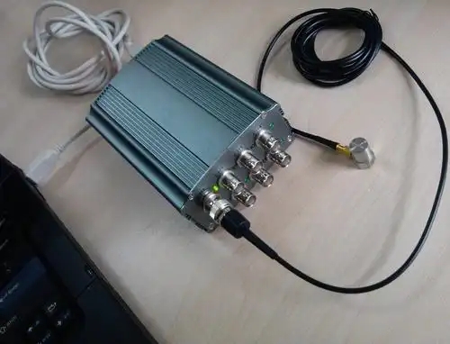
I. Project Background
As core power equipment in industrial production, motors' operational status directly impacts production line stability. Traditional manual inspections are highly lagging and prone to missed detections; dedicated monitoring equipment, on the other hand, is costly, complex to deploy, and difficult to scale.
Typical faults in rotating machinery are manifested in:
-
Vibration Signals: Abnormal amplitude, spectrum, kurtosis, and crest factor.
-
Temperature Signals: Abnormal bearing temperature, casing temperature, and winding temperature.
Therefore, vibration + temperature fusion monitoring is the most mature and reliable technical route for motor fault diagnosis.
This project designs an integrated, low-power, highly reliable online monitoring terminal based on the ZYNQ-7000 series platform, achieving:
-
Multi-channel IEPE vibration synchronous acquisition
-
Multi-channel PT100/NTC temperature acquisition
-
Hardware-level real-time data buffering
-
Embedded AI / Threshold-based diagnosis
-
Ethernet / 4G upload to platform
II. System Overall Architecture
The system adopts the classic ZYNQ PL+PS heterogeneous architecture:
Engineering and Technology
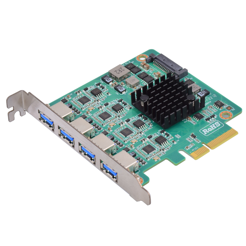
1. Hardware Layer
-
IEPE Vibration Sensors × 1~4 channels
-
Temperature Sensors (PT100) × 4~8 channels
-
Signal Conditioning Circuitry (constant current source, amplification, anti-aliasing filtering)
-
High-speed ADC, analog switches, excitation circuit
-
ZYNQ7020/7010 Core Board
-
Ethernet, power supply, isolation protection
2. FPGA (PL) is responsible for:
-
1MHz~10kHz configurable sampling rate
-
Multi-channel synchronous sampling control
-
FIFO ping-pong buffering to prevent data loss
-
Digital filtering and downsampling
-
Temperature acquisition timing control
3. ARM (PS) is responsible for:
-
Data reading and parsing under Linux system
-
Time-domain / Frequency-domain feature calculation (RMS, peak-to-peak, kurtosis, spectrum)
-
Bearing fault characteristic frequency (BPFO, BPFI, BSF, FTF) calculation
-
Temperature threshold judgment and over-temperature alarm
-
Fault level determination and local storage
-
Modbus TCP/MQTT upload to cloud
4. Data Flow
Sensor → Conditioning → ADC → PL Acquisition Buffer → AXI DMA → PS Processing → Diagnosis → Upload / Local Storage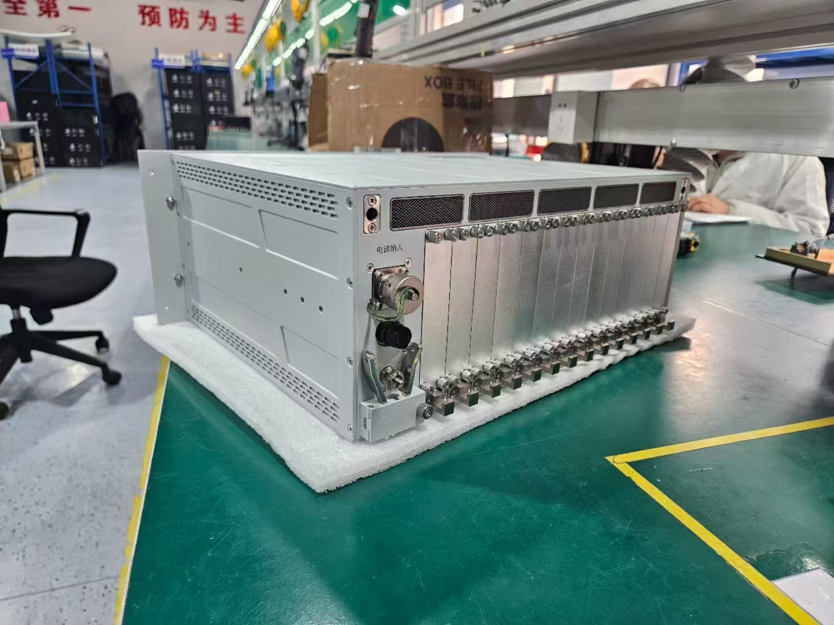
III. Key Hardware Design
1. IEPE Vibration Signal Conditioning
IEPE sensors require a 2~4mA constant current source for power, so the hardware must include:
-
Constant current source circuit (TL431 + op-amp or dedicated constant current chip)
-
AC coupling DC-blocking circuit
-
Low-pass anti-aliasing filter (cutoff frequency set according to sampling rate)
-
Level shifting circuit to adapt to ADC unipolar input
2. Temperature Acquisition Circuit
Utilizing:
-
PT100 platinum resistance temperature measurement
-
Constant current excitation + instrumentation amplifier
-
Multi-channel analog switch polling acquisition
-
Digital isolation to avoid strong electrical interference from motors
3. Grounding and Anti-Interference Design (Industrial Focus)
-
Single-point connection for analog and digital grounds
-
Power supply with added ferrite beads, LC filtering
-
TVS, RC absorption at signal input
-
Ethernet port magnetic isolation
Ensuring stable operation in strong industrial electromagnetic environments.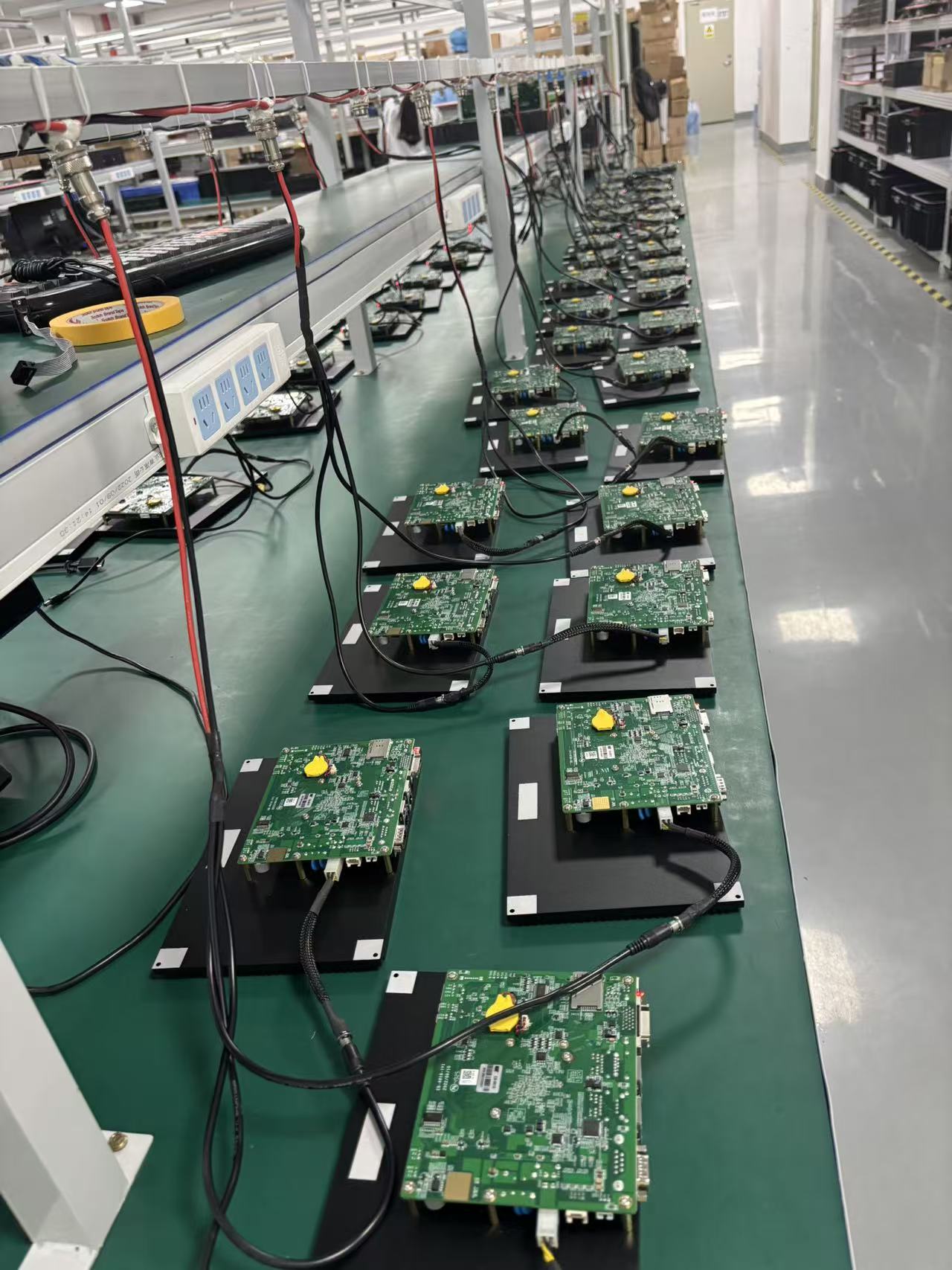
IV. FPGA (PL) Logic Design
1. Sampling Control Module
-
Built-in PLL generates precise sampling clock
-
Supports multiple configurations like 12.5k/25k/50k/100k
-
Multi-channel synchronous triggering to ensure time alignment of vibration and temperature
2. Dual Ping-Pong FIFO Buffer
With large data volumes during high-speed continuous acquisition, a ping-pong FIFO is used:
-
When FIFO A is written, FIFO B is read
-
Alternating switching, no data loss, no blocking
-
Suitable for long-term continuous acquisition
3. Simple Pre-processing (PL-side Acceleration)
-
Mean filtering
-
Truncation and data alignment
-
Oversampling averaging for noise reduction
Reduces ARM processing load and improves system real-time performance.
V. ARM (PS) Software and Fault Diagnosis Algorithms
The PS runs Linux, with the application layer implementing:
1. Data Reading
Read from PL-side FIFO via AXI DMA or AXI GP interface:
-
Raw vibration waveforms
-
Multi-channel temperature values
-
Timestamp information
2. Time-Domain Feature Calculation
-
Root Mean Square (RMS)
-
Peak-to-peak value
-
Kurtosis (sensitive to early faults)
-
Impulse factor, crest factor
3. Frequency-Domain Analysis (FFT)
Perform FFT on vibration signals to extract:
-
Rotational frequency
-
2x, 3x rotational frequency components (unbalance / misalignment)
-
Bearing fault characteristic frequencies
-
Harmonics and modulation phenomena
4. Fusion Diagnosis Logic
-
Vibration exceeding threshold → Pre-warning
-
Continuous temperature rise → Pre-warning
-
Vibration + temperature simultaneously abnormal → Severe alarm
-
Sudden change in kurtosis → Early impact-type faults (e.g., bearing pitting)
5. Upload and Storage
-
MQTT reporting to cloud platform
-
Local SD card black box storage
-
Supports real-time waveform viewing via web / PC software
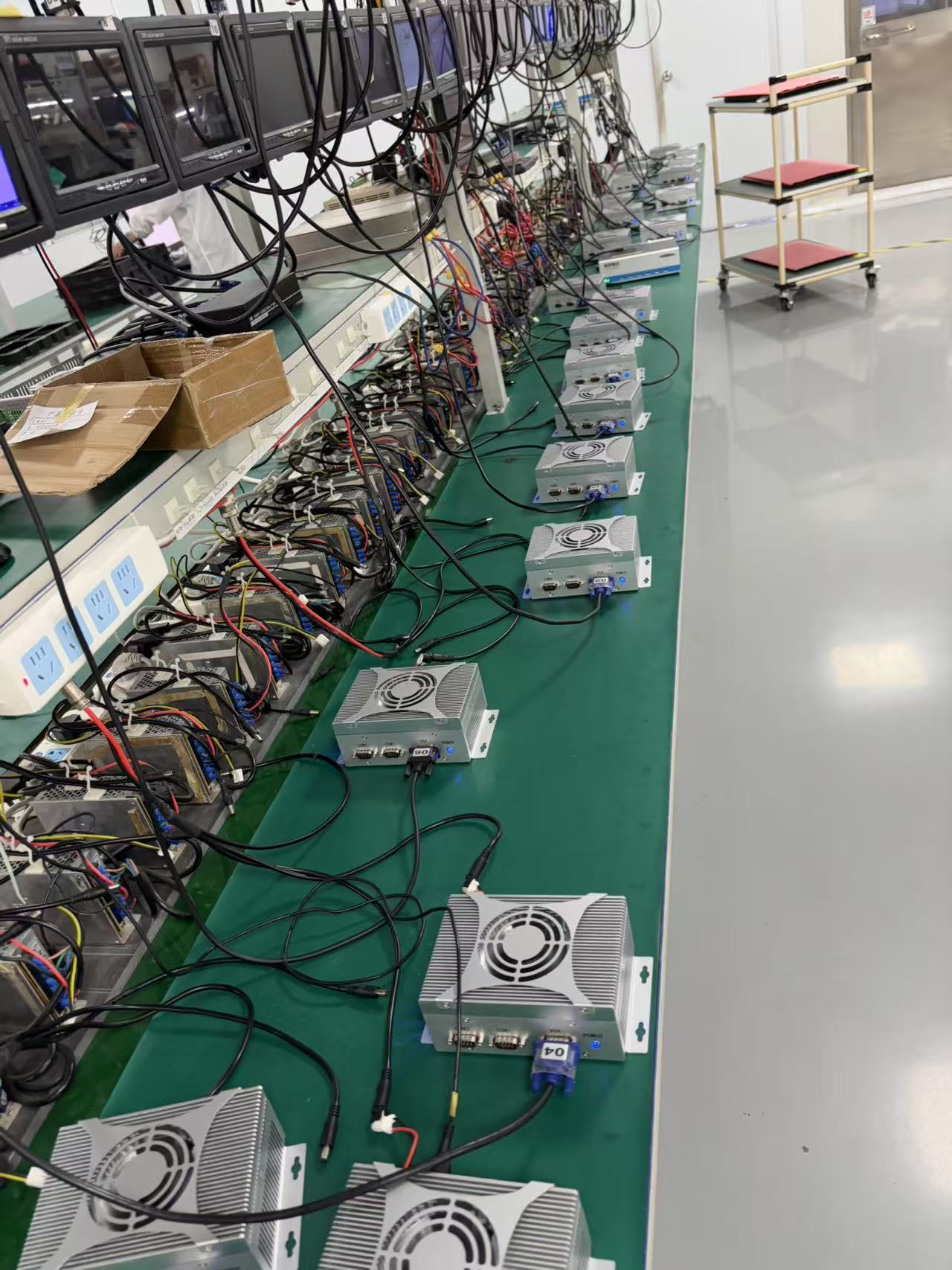
VI. Typical Motor Fault Identification Capabilities
This terminal can effectively identify:
-
Rotor Unbalance Significant increase in 1x rotational frequency vibration
-
Coupling Misalignment Pronounced 2x, 3x rotational frequency components
-
Bearing Wear / Pitting Increased kurtosis, appearance of characteristic frequencies like BPFO/BPFI
-
Looseness (Base / End Cover) Increased low-frequency amplitude, chaotic spectrum
-
Stator / Electrical Faults Appearance of power frequency harmonic components in vibration
-
Overheating Risk Continuous rise in temperature curve
VII. System Advantages
-
ZYNQ Heterogeneous Advantage PL handles high-speed acquisition, PS handles intelligent diagnosis, achieving high efficiency through hardware-software co-design.
-
Strong Synchronicity Vibration and temperature data come with unified timestamps, facilitating correlation analysis.
-
Industrial-Grade Reliability Isolation, anti-interference, fanless, wide-temperature design.
-
Easy Deployment Standard Ethernet interface, compatible with MES, SCADA, and equipment cloud platforms.
-
Controllable Cost Over 50% cost reduction compared to imported equipment, suitable for large-scale deployment.
VIII. Application Scenarios
-
Online monitoring of high-voltage motors, asynchronous motors
-
Group control of fans, water pumps, air compressors
-
Fault pre-warning for gearboxes, reducers
-
Predictive maintenance for rotating equipment in coal mines, metallurgy, chemical industries
-
Data acquisition terminal for smart factory equipment digital twins