ZYNQ High-Speed Data Acquisition Card Design: Achieving IEPE Sensor Signal Acquisition at 1M Sample Rate
ZYNQ High-Speed Data Acquisition Card Design: Achieving IEPE Sensor Signal Acquisition at 1M Sample Rate (Complete Solution)
📌 Article Summary: This article addresses industrial vibration and equipment fault detection scenarios by designing a ZYNQ-based IEPE sensor high-speed data acquisition card, achieving 1MSPS (1M sample rate) high-precision synchronous acquisition. It fully leverages the dual-core advantages of ZYNQ FPGA's high-speed parallel acquisition and ARM's embedded data processing and transmission capabilities. This approach solves the problems of low acquisition rates and poor real-time performance in traditional microcontrollers, and the high cost and limited customization of commercial acquisition cards. The complete article covers hardware circuit design, FPGA acquisition logic, ARM data parsing, practical testing and verification, and troubleshooting optimization, making it directly applicable for engineering implementation and project iteration.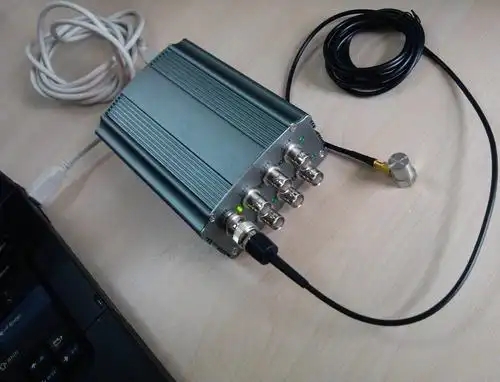
🔑 Keywords: ZYNQ7000, 1M Sample Rate, IEPE Sensor, High-Speed Data Acquisition, FPGA+ARM, Vibration Acquisition
1. Project Background and Requirements Analysis
1.1 Application Scenarios
IEPE (piezoelectric) sensors are widely used in industrial equipment vibration detection, mechanical fault diagnosis, acoustic testing, impact signal acquisition, and other scenarios. They offer advantages such as high sensitivity, strong anti-interference capability, and stable long-distance transmission. The core requirements for data acquisition systems in these scenarios are: high sample rate, high precision, real-time transmission, and stable excitation current supply.
Traditional acquisition solutions have obvious shortcomings:
-
Microcontroller/STM32 Acquisition: Insufficient ADC sample rate, unable to meet 1M high-speed acquisition requirements; large serial transmission delay, prone to losing high-frequency signals;
-
Commercial NI Acquisition Cards: High cost, large size, and difficult to customize, making them unsuitable for embedded integration scenarios;
-
Pure FPGA Acquisition Solutions: Lack operating system support, making data storage, host PC interaction, and data pre-processing feature development cumbersome.
1.2 Core Design Specifications
Combining the high-frequency signal acquisition requirements of IEPE vibration sensors, the core parameters of this acquisition card are as follows:
-
Sample Rate: Up to 1MSPS (1M sample rate), single channel can achieve stable continuous acquisition;
-
Compatible Sensors: Standard IEPE piezoelectric sensors, supporting constant current excitation power supply;
-
Acquisition Precision: 16-bit ADC high-precision sampling, meeting industrial detection precision requirements;
-
Architectural Division of Labor: FPGA is responsible for high-speed AD acquisition, data caching, and timing control; ARM is responsible for data parsing, pre-processing, and network/serial transmission;
-
Transmission Method: Supports real-time upload via Gigabit Ethernet and local cache storage;
-
Stability: Supports long-term continuous acquisition without data loss or timing errors.
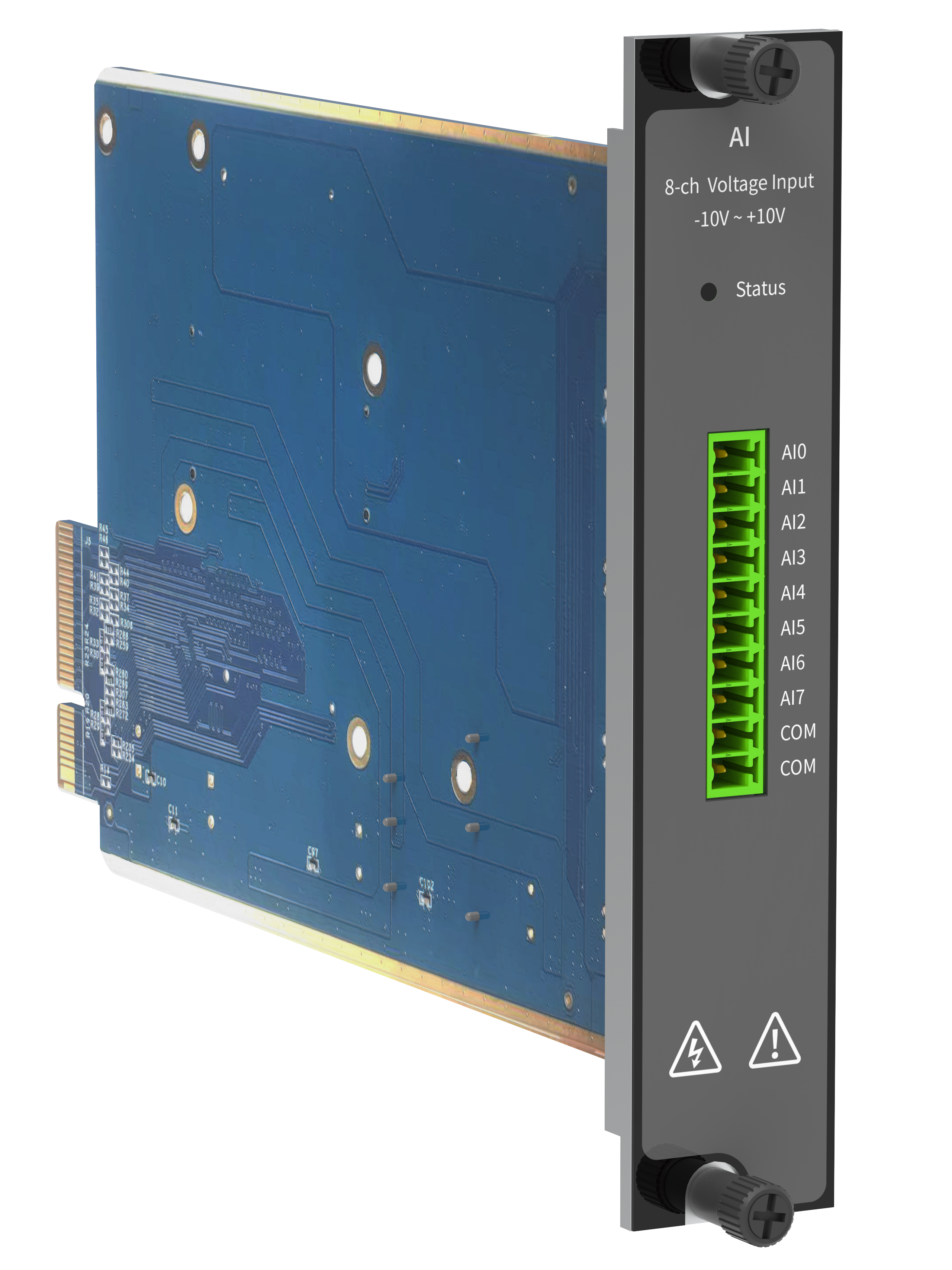
2. Overall System Architecture Design
This system adopts a ZYNQ FPGA+ARM heterogeneous architecture, fully leveraging the advantages of FPGA's parallel high-speed computation and ARM's flexible business processing. The overall architecture is clearly layered, with each component performing its specific role, perfectly matching the real-time requirements of 1M high-speed acquisition.
2.1 System Block Diagram
Signal Flow: IEPE Sensor → IEPE Signal Conditioning Circuit → High-Speed ADC Module → FPGA Acquisition Cache Logic → ZYNQ PS (ARM) → Data Pre-processing/Storage/Host PC Transmission
2.2 Module Function Division
-
FPGA (PL) Side: Configures ADC operating timing, precise 1M rate sampling, FIFO dual-buffer data storage, eliminates data jitter, and synchronous timing control, solving high-speed acquisition data overflow and packet loss issues;
-
ARM (PS) Side: Equipped with an embedded Linux system, reads PL-side cached data, performs data filtering, RMS/peak-to-peak value calculation, data packaging, real-time upload via Gigabit Ethernet, and local log storage;
-
Conditioning Circuit: Provides standard constant current excitation for IEPE sensors, signal amplification, anti-aliasing filtering, and voltage matching, ensuring the purity of the original signal.
3. Hardware Circuit Detailed Design
The core hardware consists of three main modules: IEPE Sensor Constant Current Conditioning Circuit, 1M High-Speed ADC Acquisition Circuit, and ZYNQ Minimum System Circuit, which form the hardware foundation for achieving high-speed and high-precision acquisition.
3.1 IEPE Sensor Conditioning Circuit Design
Unlike ordinary voltage sensors, IEPE sensors require 4mA constant current excitation power supply to operate normally. They output weak voltage vibration signals, which need to be amplified and filtered before being fed into the ADC.
-
Constant Current Source Circuit: Uses a high-precision constant current chip to build a 4mA standard excitation circuit, with a current accuracy of ±0.1mA, compatible with most industrial IEPE vibration sensors, ensuring stable sensor operation;
-
Signal Amplification Circuit: Uses a low-noise operational amplifier to differentially amplify the weak output signal from the sensor, increasing signal amplitude and reducing acquisition noise;
-
Anti-Aliasing Filter Circuit: Designs a second-order active low-pass filter, configuring the cutoff frequency according to the 1M sample rate to filter out high-frequency interference noise, prevent spectral aliasing, comply with the Nyquist sampling theorem, and ensure the integrity of high-frequency vibration signal acquisition.
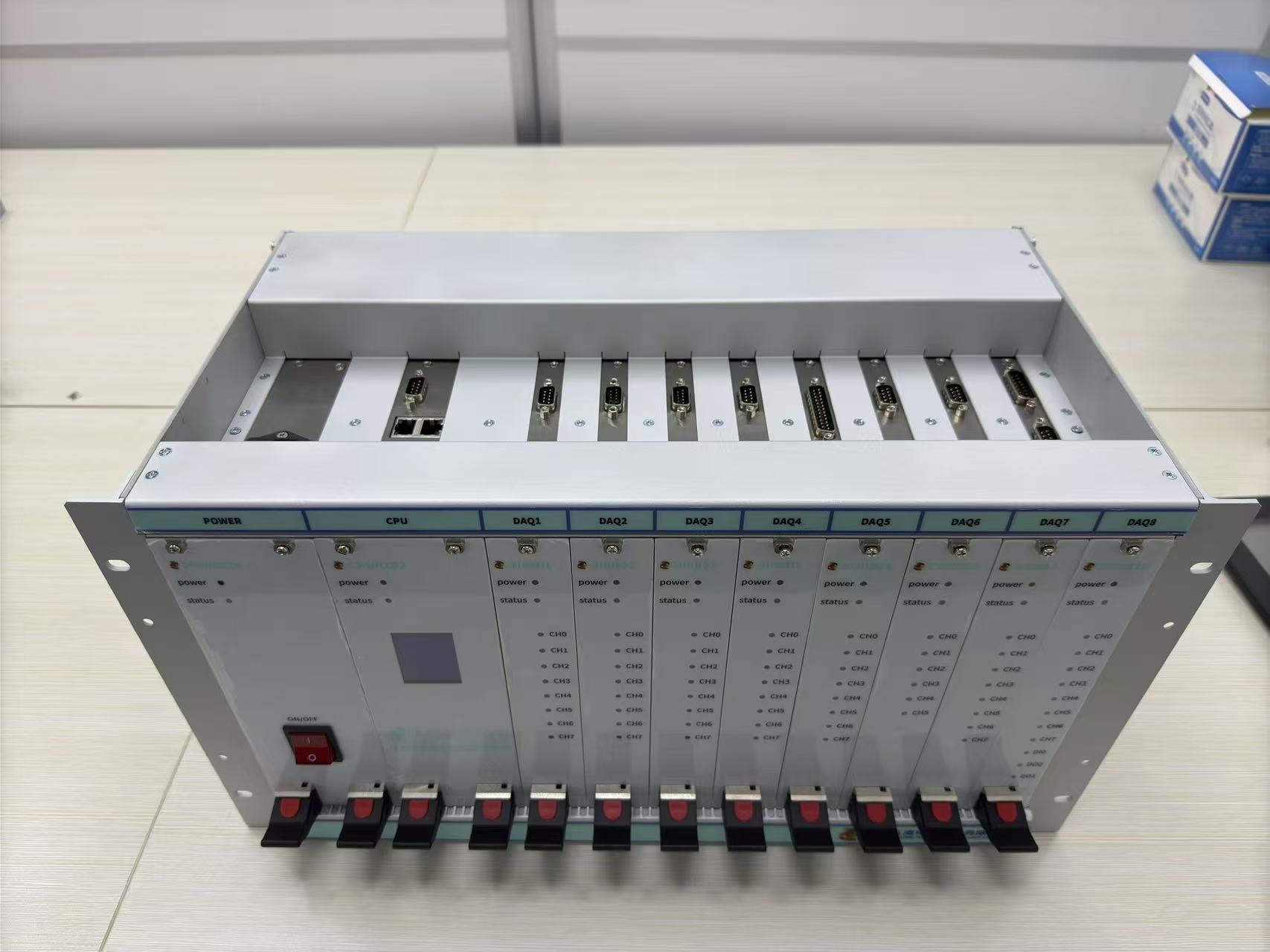
3.2 High-Speed ADC Module Selection and Circuit
To meet the 1MSPS high-speed sampling + 16-bit high-precision requirements, this design selects the AD8268 high-speed analog-to-digital converter chip, which supports a single-channel maximum sample rate of 1.2MSPS, fully covering the 1M design specifications. It features low power consumption, low noise, and good linearity, making it suitable for high-precision acquisition of vibration signals.
Key points of circuit design:
-
The ADC reference power supply uses a high-precision, low-drift reference source to ensure sampling voltage stability and reduce sampling errors;
-
Analog ground and digital ground are single-point grounded, and power domains are separated to prevent digital high-frequency noise from interfering with analog acquisition signals;
-
The ADC data interface is directly connected to the ZYNQ PL-side I/O, enabling parallel data transmission to minimize transmission delay and support 1M high-speed sampling.
3.3 ZYNQ Minimum System Design
The core uses ZYNQ7010/7020 general-purpose industrial-grade chips. The PS side is equipped with 512MB DDR3 memory and 32MB QSPI Flash to ensure stable operation of the