Key Design Points for PT/CT AC Sampling in Microgrid/Coordination Controllers: 4U Modular and 1U Simplified Designs
Key Design Points for PT/CT AC Sampling in Energy Storage Coordination Controllers
In energy storage coordination controllers (PCS/EMS/BMS coordinated control), PT/CT AC sampling is a core component for power calculation, protection logic, grid-connection point monitoring, and PQ regulation. It directly impacts control accuracy, grid stability, and protection reliability. The key design points are summarized below.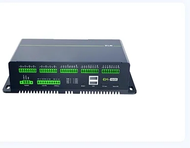
I. General Design Principles
-
Meet grid-connection metering-grade accuracy. General requirements: Voltage/current sampling accuracy **≤0.2%\****0.5%** (sic), active/reactive power accuracy **≤0.5%\**1% (sic).
-
Strong anti-interference. Energy storage sites often experience harmonics, switching noise, and large current impacts, so isolation, filtering, and grounding are essential.
-
Wide range and overload capability. Support voltage sags, swells, and short-circuit impacts. CT/PT requires 1.2~2 times the rated range.
-
Synchronous sampling. Three-phase voltage and current must be sampled simultaneously, otherwise, power calculation errors will be significant.
-
Meet protection speed requirements. Total sampling delay (including conditioning + ADC + calculation) should ideally be <1ms to meet over/under voltage, overcurrent, and islanding protection responses.
II. PT/CT Selection and Electrical Interface Key Points
1. Voltage Transformer (PT)
-
Common transformation ratios: 10kV/0.1kV, 0.4kV/0.1kV
-
Accuracy class: 0.2 class / 0.5 class, not recommended to be lower than 0.5 class
-
Output: 100V (line voltage) or 57.7V (phase voltage)
-
Secondary side must not be short-circuited; requires fuses / miniature circuit breakers
-
Isolation withstand voltage: ≥2.5~3kV, meeting safety regulations and common-mode interference requirements
2. Current Transformer (CT)
-
Transformation ratio selected based on rated current: e.g., 200/5A, 400/5A, 800/5A
-
Accuracy: 0.2S/0.5S class (accuracy is more critical at low currents)
-
Secondary side must not be open-circuited; must be short-circuited or connected to the sampling circuit
-
Supports through-hole / busbar type installation for convenient engineering wiring
-
Energy storage inverters have high harmonics, so prioritize low remanence, anti-saturation CTs
3. Signal Conditioning Methods
-
Current side: CT 5A → Precision sampling resistor (20~50mΩ) → Voltage signal
-
Voltage side: PT 100V → Precision resistive voltage divider network → Low voltage signal
-
Before entering ADC: Op-amp buffer + second-order active low-pass filter
III. Signal Conditioning and Hardware Circuit Key Points
-
Electrical Isolation
-
Must use linear optocouplers / isolated op-amps / isolated ADCs
-
Strictly separate power ground and signal ground to avoid ground loops introducing interference
-
-
Filtering Design
-
Cut-off frequency: 100~200Hz to filter out switching harmonics
-
While retaining the fundamental wave (50/60Hz) to avoid phase shift
-
-
Bias Shifting
-
Shift the AC signal to a common-mode voltage of 1.25V/2.048V/2.5V
-
To adapt to unipolar ADC input ranges (0\3.3V or 0\5V) (sic)
-
-
Anti-aliasing Filtering
-
ADC sampling rate is typically ≥16kHz
-
An anti-aliasing filter must be present at the front end to prevent high-frequency noise aliasing
-
-
Temperature Drift Control
-
Sampling resistors and voltage divider resistors should be selected for low temperature drift (within ±25ppm/℃)
-
Op-amps should be low offset, low drift types
-
IV. ADC and Synchronous Sampling Key Points
-
Multi-channel Synchronous Sampling
-
Three-phase Ua, Ub, Uc, Ia, Ib, Ic must be sampled simultaneously
-
It is recommended to use simultaneous sampling ADCs (e.g., ADS8568, AD7606, etc.)
-
-
Sampling Frequency
-
For a 50Hz fundamental wave, 32 points/cycle or 64 points/cycle are commonly used
-
i.e., sampling rate: 1.6kHz / 3.2kHz, meeting harmonic and protection calculation requirements
-
-
Phase Calibration
-
PT/CT and filtering circuits can introduce phase shift
-
Software compensation is essential; otherwise, power factor and reactive power errors will be significant
-
-
Reference Source Accuracy
-
External high-precision reference source (e.g., 2.048V/4.096V)
-
Avoid using the MCU's internal reference source, which may lead to insufficient accuracy
-
V. Software Algorithm Design Key Points
-
RMS Calculation
-
One-cycle integration method:
U_{rms}=\sqrt{\frac{1}{N}\sum u_i^2},\quad I_{rms}=\sqrt{\frac{1}{N}\sum i_i^2U_{rms}=\sqrt{\frac{1}{N}\sum u_i^2},\quad I_{rms}=\sqrt{\frac{1}{N}\sum i_i^2
-
-
Power Calculation
-
Instantaneous power method:
P=\frac{1}{N}\sum u_i i_i,\quad Q=\text{正交分量积分P=\frac{1}{N}\sum u_i i_i,\quad Q=\text{正交分量积分
-
-
Frequency Tracking
-
Zero-crossing detection or Software Phase-Locked Loop (Software PLL)
-
Ensure accurate one-cycle sampling even when not at 50Hz
-
-
Harmonic Suppression
-
Supports calculation or filtering of at least the 13th harmonic
-
Meets energy storage grid-connection power quality monitoring requirements
-
-
Anomaly Detection
-
Disconnection detection (PT/CT open circuit)
-
Overvoltage, overcurrent, and spike impact rejection
-
Prevent false protection trips
-
VI. Engineering and Reliability Key Points
-
Wiring Specifications
-
PT/CT secondary wiring should use shielded twisted pair cables
-
Shielding should be grounded at one end to avoid multiple ground loops
-
-
Grounding Design
-
Separate power ground, signal ground, and protection ground
-
Sampling board single-point grounding to reduce common-mode interference
-
-
Temperature Drift and Long-term Stability
-
Implement automatic calibration / zero-point calibration mechanisms
-
Support external standard source calibration
-
-
Protection Logic Coordination
-
Sampling data is used for:
-
Over/undervoltage protection
-
Overcurrent/short-circuit protection
-
Islanding protection
-
Grid synchronization detection
-
-
-
EMC Design
-
Add TVS diodes, varistors, and common-mode inductors
-
To prevent lightning strikes and surges from damaging the sampling circuit
-
VII. Typical Performance Indicators
-
Voltage sampling accuracy: ≤±0.5%
-
Current sampling accuracy: ≤±0.5%
-
Active/reactive power accuracy: ≤±1%
-
Phase error: ≤±0.5°
-
Total delay: <1ms
-
Supported frequency range: 45~55Hz
-
Anti-interference compliance: EN61000-6-2 / EFT, surge immunity level