ZYNQ MPSOC-based Ship Data Acquisition Instrument Design (Part 2): EMC Reliability Design
Main Control Board Circuit Design
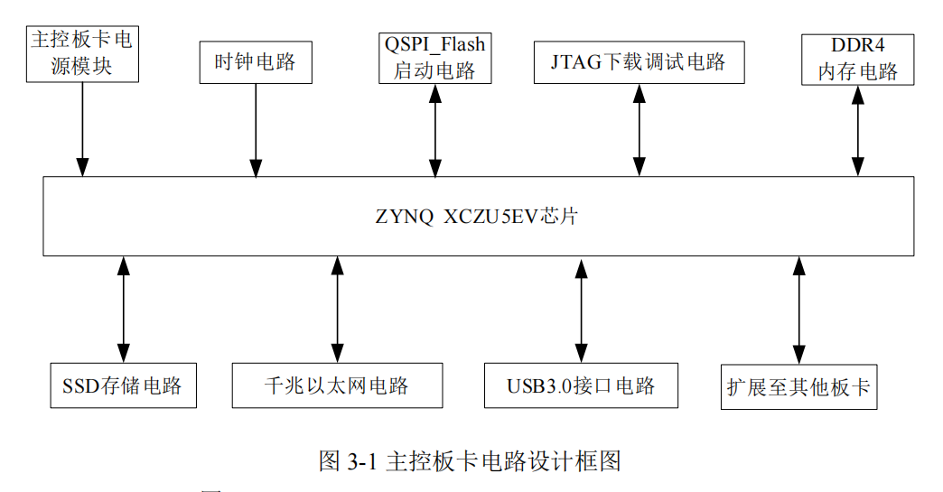
The main control board circuit design is shown in Figure 3-1, primarily including the peripheral circuits of the main control chip and the design of some functional circuits.
3.5 Electromagnetic Compatibility Design for Cabin Environment
Electromagnetic interference in a ship environment is complex and variable. To ensure stable and reliable operation of the data acquisition and recording device, electromagnetic compatibility (EMC) design must be emphasized in hardware design. This design adopted the following EMC measures:
(1) Hardware Circuit Electromagnetic Compatibility Design:
In the circuit design of this system, particular attention was paid to power quality and signal integrity:
① Each power node is configured with decoupling capacitor filtering, using 10μF and 0.1μF capacitors in parallel to filter out low-frequency and high-frequency interference respectively, ensuring stable power voltage;
② Multi-stage decoupling capacitor filtering is arranged near the power pins of critical chips (such as ZYNQ processors, ADC chips).
(2) PCB Layout and Routing Optimization
PCB design adheres to strict EMC principles:
① Layout is clearly divided by functional modules, with digital and analog circuits physically isolated;
② Digital ground and analog ground are separated and use single-point grounding;
③ High-frequency circuits (Gigabit Ethernet interface, DDR4, etc.) use equal-length routing and impedance matching techniques to improve signal quality;
④ Differential signals such as CAN bus employ strict differential pair routing to enhance signal anti-interference capability and reduce electromagnetic radiation.
(3) Shielding and Enclosure Design
Comprehensive shielding measures are adopted for the high electromagnetic interference environment on ships:
① The system uses a full-metal aluminum alloy enclosure design with a thickness of 1.5mm, preventing electromagnetic interference generated inside the device from leaking out, while effectively shielding external electromagnetic radiation;
② Input EMI filters and TVS protection circuits are used to prevent conducted interference from power lines and transient overvoltage.
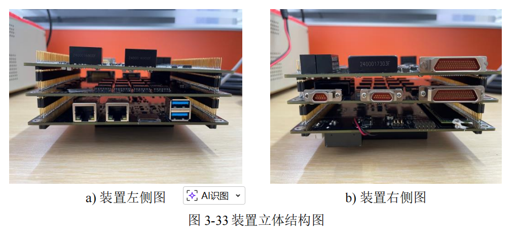
To further reduce electromagnetic radiation, an external aluminum alloy chassis (480×410×100mm) is added, equipped with multi-parameter input interfaces, a power switch, and network cable holes. An anti-vibration base is installed at the bottom. The structure is shown in Figure 3-34.
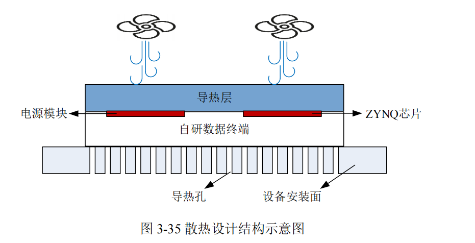
3.6.2 Thermal Design
Since ship compartments may be high-temperature environments, to prevent the device's functional operation from being affected by excessive temperature, thermal management is required for high-power consumption chips on the board.
Thermal solution: Heat is conducted using designed thermal strips, and dissipated through thermal holes (13mm×13mm) in the device's mounting base. High-power consumption chips such as the ZYNQ and DC-DC power supply are designed to be installed on the exterior of the board, effectively reducing the temperature of these high-heat chips through the thermal layer and thermal holes. A specific schematic of the thermal design is shown in Figure 3-35.
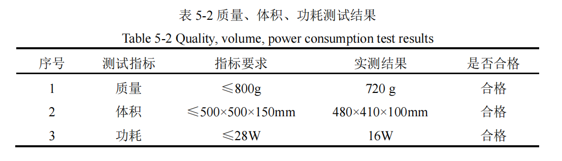
5.2 Weight, Volume, and Power Consumption Testing
As shipborne equipment has specific requirements for weight, volume, and power consumption, these indicators were tested. The test results are shown in Table 5-2.