FPGA+USB+CCD High-Precision Industrial Camera for Precision Object Measurement and Machining Accuracy
FPGA + USB + CCD High-Precision Industrial Camera for Object Measurement and Machining Accuracy
Precision manufacturing depends on accurate, real-time visual inspection. When tolerances are measured in microns, the imaging pipeline itself — sensor, signal chain, interface, and software — must be engineered as a cohesive system rather than a collection of off-the-shelf parts. This post describes a purpose-built industrial camera platform combining an FPGA, a Sony CCD image sensor, and a USB 2.0 interface, designed specifically for precision object measurement and machining accuracy verification on the factory floor.
Why FPGA + CCD Instead of CMOS-Based Solutions?
Most consumer and prosumer machine-vision cameras have shifted to CMOS sensors because they are cheaper and easier to read out. For industrial metrology, CCD sensors — particularly Sony's low-noise CCD lineup — still offer advantages: lower dark current, better pixel uniformity, and a global shutter that eliminates the rolling-shutter distortion that plagues CMOS sensors when imaging fast-moving workpieces. The tradeoff is that CCD readout requires careful analog front-end design and precise timing control, which is exactly where an FPGA earns its place.
The FPGA takes over all time-critical functions: CCD clock generation, correlated double sampling (CDS) control, analog-to-digital conversion timing, and pixel pipeline processing. This keeps the image path deterministic and free from operating-system jitter — a property that matters when a single dropped or delayed frame can cause a measurement outlier.
System Architecture Overview
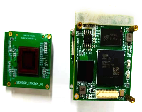
At a high level the platform consists of three layers:
- Sensor and analog front end — A Sony low-noise CCD captures the scene. Supplementary LED ring lighting and an optional microscopic magnifier lens bring the working distance and field of view down to the level required for small-component inspection.
- FPGA core — The FPGA handles CCD timing, pixel data capture, and real-time image processing (motion detection, contour recognition). Processed frames are buffered and handed off to the USB controller.
- USB 2.0 host interface — The camera exposes itself to the PC either as a standard UVC (USB Video Class) device or via a custom vendor-class driver, depending on the integration requirement.

Key Technical Features
1. Sony Low-Noise CCD Support
The platform is designed around Sony's CCD sensors, chosen for their excellent signal-to-noise ratio and pixel-level uniformity. Low read noise is essential in metrology: when you are detecting the edge of a machined surface under controlled illumination, noise that shifts the apparent edge location by even a fraction of a pixel translates directly into measurement error.
2. One-Frame Acquisition-to-Display Latency
The FPGA processes and forwards each frame to the USB controller within a single frame period. On the PC side, the host software renders the live feed with only that one-frame pipeline delay. For an operator manually aligning a workpiece under a microscope, sub-frame latency makes the difference between a responsive, usable tool and one that feels laggy and unreliable.
3. USB 2.0 with UVC and Custom Driver Options
Shipping a UVC-compliant device means plug-and-play compatibility: any Windows, Linux, or macOS host recognizes the camera without driver installation. For integrators who need access to proprietary camera controls not exposed by the UVC specification, a custom vendor-class driver is also available. This dual-mode strategy covers both quick evaluation setups and deeply integrated production-line deployments.
4. Microscopic Magnifier and Supplementary Lighting
The optical assembly supports attachment of a microscopic magnifier for close-up inspection of fine features — solder joints, machined threads, stamped edges, and similar details. An integrated supplementary LED light source ensures consistent, controlled illumination independent of ambient factory lighting, which is a prerequisite for repeatable edge-detection and measurement results.
5. PC Host Software for CCD Parameter Adjustment
A Windows-based host application exposes the full set of CCD operating parameters — gain, exposure time, black-level offset, and white balance — through a graphical interface. Operators can tune the sensor for different materials and surface finishes (polished metal reflects very differently from anodized aluminum or plastic) without touching firmware or driver code.
6. PC SDK for Integration into Professional Measurement Software
A software development kit (SDK) wraps the camera's data stream and control interface in a clean API, making it straightforward to embed the camera into established metrology packages. Measurement software can call SDK functions to grab frames, trigger acquisition, and read back image data in standard formats, rather than having to implement USB protocol handling from scratch.
7. Print and Data Export from the Host Application
The host software includes print and data export functionality. Inspection results — dimensional measurements, pass/fail stamps, annotated images — can be sent directly to a label printer or exported in formats compatible with quality management systems. This closes the loop from visual inspection to production record without manual transcription.
8. Object Motion Detection (MOD)
The FPGA implements a motion detection algorithm in hardware. When a workpiece enters or leaves the field of view, the system can trigger an automatic capture or alert the host application. In automated inspection lines this eliminates the need for a separate trigger sensor, reducing wiring complexity and potential points of failure.
9. Object Contour Recognition
Edge and contour extraction runs on the FPGA in real time, overlaying the recognized outline on the live video feed. The PC software can use these contour data — or export them — as the basis for dimensional comparison against a reference profile, enabling go/no-go decisions directly from the image without post-processing delays.
Practical Deployment Considerations
- Lighting stability: CCD sensors are linear but the measurement chain is only as stable as the illumination. Use DC-driven LEDs rather than PWM-dimmed ones if the shutter speed is shorter than the PWM period, to avoid flicker artifacts in captured frames.
- Vibration isolation: Micron-level measurements are sensitive to mechanical vibration. Mount the camera and workpiece on a rigid, vibration-isolated surface.
- USB cable length: USB 2.0 is rated to 5 m. Beyond that, use an active extension cable or a USB hub with its own power supply to prevent signal integrity issues that can cause dropped frames.
- Driver selection: Start with UVC for initial integration; switch to the custom driver only when you need camera controls or frame metadata not available through the standard interface.
Summary
This FPGA + USB + CCD industrial camera platform is a vertically integrated solution targeting precision metrology applications where image quality, latency, and software flexibility all matter. By combining a Sony low-noise CCD with FPGA-based timing and real-time processing, a dual-mode USB interface, and a full-featured PC SDK, the system can be deployed as a standalone inspection station or embedded inside professional measurement software with minimal integration effort.