OMAPL138 Duntai I2C LCD Touchscreen Driver Porting
OMAPL138 Duntai I2C LCD Touchscreen Driver Porting
In this article, we will explore the process of porting the GT811 touchscreen driver for the OMAPL138 platform, specifically focusing on the hardware analysis and software configuration required to establish a connection via the I2C interface. By the end of this post, you will have a clear understanding of the necessary steps to configure the I2C pins and handle the interrupt and reset functionalities for the GT811 LCD touchscreen.
Hardware Analysis
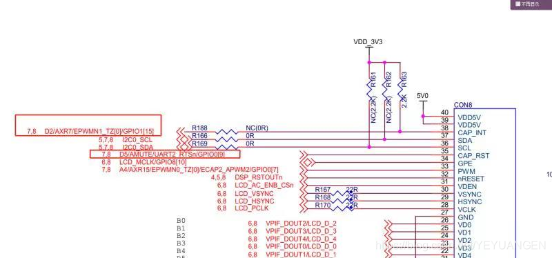
The GT811 touchscreen controller connects to the OMAPL138's I2C1 interface. To ensure proper communication, it is essential to configure the corresponding pins on the AM335x for I2C functionality.
Software Configuration
To facilitate the communication between the GT811 and the OMAPL138, we need to configure two primary pins associated with I2C1:
-
GPIO1_27: This pin must be set up as an interrupt input that is triggered on the falling edge. The interrupt number for this pin can be determined, as it corresponds to pin 27 of GPIO1. The kernel has the capability to convert the pin number into an interrupt number for processing.
-
GPIO1_26: This pin is utilized for the RESET functionality. During the initialization of the GT811, the driver must manipulate the RESET pin, which requires a low signal to reset the device. Therefore, GPIO1_26 should be configured as an output pin set to a specific level.
From previous articles, we understand that Device Tree Source (DTS) files can be used to configure pin multiplexing (pinmux). By analyzing the kernel's existing DTS files, we can confirm that the DTS can also relay connection information to the kernel.
Modifications to the TQ335x.dts File
After careful analysis and reference, the following modifications were made to the TQ335x.dts file to accommodate the GT811 touchscreen driver:
Step 1: Check I2C Pinmux Configuration
To verify the I2C pinmux configuration, search for the i2c1 node within the DTS file. The pinctrl-0 property of this node points to a phandler that configures the two pins associated with i2c1. Upon review, it was determined that no modifications are needed for this section, as the configuration is already correct.
Step 2: Configure INT and RESET Pins
Next, we need to add pin configuration information for the INT and RESET pins within the am33xx_pinmux node. This addition will ensure that the necessary configurations for GPIO1_27 and GPIO1_26 are correctly set up in the device tree.
The specific details for the pin configuration should include the following:
- GPIO1_27: Set as an interrupt input, falling edge triggered.
- GPIO1_26: Set as an output pin for the RESET functionality.
By implementing these changes, the GT811 touchscreen driver will be properly configured to communicate with the OMAPL138 via the I2C interface, enabling touch functionality on the LCD display.
Conclusion
Porting the GT811 touchscreen driver to the OMAPL138 platform involves careful hardware analysis and precise software configuration. By following the outlined steps and making the necessary modifications to the TQ335x.dts file, you can successfully establish communication between the touchscreen and the processor. This process not only enhances the functionality of your embedded system but also provides a solid foundation for further development and integration of additional features.