Design of an 8K Smart Camera Solution Based on RK3588
Design of an 8K Smart Camera Solution Based on RK3588
High-resolution imaging has entered a new era as 8K displays (7680×4320, approximately 33 million pixels) move from broadcast studios into consumer living rooms. Building a camera system that can feed those displays end-to-end — from sensor to screen — demands careful co-selection of processor, image sensor, interconnect, and thermal management. This article walks through the hardware architecture of an 8K smart camera built around the Rockchip RK3588 SoC and Sony IMX435 sensor, with graphene-based heat dissipation, and covers the key PCB layout rules that keep the system stable in production.
System Architecture
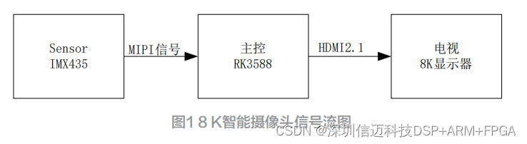
The signal chain is straightforward but demanding at every stage:
IMX435 → MIPI CSI-2 → RK3588 (ISP + encode) → HDMI 2.1 → 8K TV
The Sony IMX435 captures raw 8K imagery and streams it over MIPI differential pairs to the RK3588. The SoC's on-chip ISP decodes and processes the raw frames, then the encoded output leaves the board via HDMI 2.1 to reach the display. The entire pipeline delivers a true end-to-end 8K presentation with no resolution compromise. The system is powered by a 5 V / 2 A adapter, keeping the overall power budget modest given the performance on offer.
Key Components
RK3588 — Main Processor
The Rockchip RK3588 is built on an octa-core 64-bit heterogeneous CPU cluster: four Cortex-A76 performance cores running at up to 2.4 GHz and four Cortex-A55 efficiency cores running at 1.8 GHz. The die integrates approximately 6 billion transistors. On-chip AI acceleration is provided by a 6 TOPS NPU, enabling real-time inference tasks such as object detection and scene analysis directly on the camera without cloud offload.
For imaging specifically, Rockchip fitted the RK3588 with a third-generation ISP (8K-capable) that supports multi-camera input, wide dynamic range enhancement, 3D noise reduction, and lens distortion correction — all in silicon. The chip also exposes a rich peripheral set: USB 3.1, USB 2.0, PCIe 3.0, PCIe 2.0, and USB Type-C, making it straightforward to add storage, networking, or other peripherals. Both Android and Linux are supported OS targets.
Sony IMX435 — Image Sensor
The IMX435 is a back-illuminated stacked CMOS sensor capable of capturing 8K video at up to 60 frames per second, placing it at the top of Sony's cost-efficient imaging lineup. A standout feature is its Natural Conversion Gain technology, which improves signal-to-noise ratio in low-light conditions by varying the conversion gain without switching pixel modes. The sensor also offers six native ISO settings — ISO 50, 200, 800, 12800, 102400, and 163840 — giving the imaging pipeline wide latitude for exposure control without introducing digitally synthesized gain.
Graphene Heat Spreader
In a compact camera enclosure, heat has nowhere to go. The RK3588 and IMX435 together generate significant thermal load, and junction temperature directly affects both image quality (via dark current and noise) and long-term reliability. This design addresses the problem with a graphene heat spreader. Graphene is currently the highest thermal-conductivity carbon material available, with a measured in-plane thermal conductivity of approximately 5300 W/m·K — several times higher than copper (~400 W/m·K). Applied between the chip packages and the enclosure, graphene efficiently moves heat away from the dies, keeping the system thermally stable under sustained 8K workloads.
Hardware Circuit Design
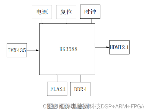
The camera PCB is organized into four major sub-circuits: main control, sensor interface, power, and clock/reset. The schematic block is shown below.
Clock and Reset
The RK3588 system clock is derived from a 24 MHz crystal oscillator combined with internal feedback circuitry. The chip's nPOR reset pin is active-low; a reset pulse longer than 4 µs guarantees stable initialization. Crystal routing on the PCB follows strict rules: XIN and XOUT traces must be ground-shielded (guard traces connected to GND) for their full length, must have a continuous reference ground plane beneath them, must not cross any power planes or high-speed signals, and must pass through no more than two vias. The oscillator package is placed as close to the RK3588 as physically possible to minimize trace inductance.
Power Supply and Decoupling
Several independent supply rails feed the RK3588, each with its own layout requirements:
- PLL supplies — PLL_AVDD_0V8 and PLL_AVDD_1V8 must be isolated from other rails. Decoupling capacitors must sit immediately adjacent to their respective pins to prevent reference noise from corrupting the PLLs.
- CPU core (0.8 V) — The LDO powering the CPU cores must be rated for more than 1.5 A. PCB capacitors must be placed as close to the chip pins as possible; remote placement causes supply noise and system instability.
- Logic and NPU core (0.8 V) — The LDO for logic and NPU must be rated for more than 2 A, with the same tight-placement rule for capacitors.
- LPDDR4 (1.1 V) — All DDR memory devices must share a single power network (VCC_DDR). The reference voltage Vref_CA is generated by a resistor divider from VCC_DDR; 1% precision resistors are specified to hold the divider ratio accurate.
DDR Routing
DDR signal integrity is maintained through controlled impedance and length matching:
- All signals within a DDR byte group and between adjacent byte groups must observe the 3W rule (trace-to-trace spacing ≥ 3× trace width).
- CLKP/CLKN differential pair length mismatch must remain under 5 mil.
- DQS, DM, and DATA signal length mismatch must remain under 10 mil.
- DQSnP/DQSnM differential pair length mismatch must remain under 5 mil.
FLASH Routing
Flash signal traces must not cross power-plane splits, preserving a continuous reference plane under the signals. Adjacent signal trace spacing follows the 3W rule throughout.
MIPI CSI-2 Sensor Interface
The IMX435 connects to the RK3588 via MIPI CSI-2 differential pairs. Routing rules for these lanes:
- A solid GND reference plane must underlie the MIPI traces without interruption.
- Differential pair intra-pair skew must be less than 5 mil.
- Differential trace impedance must be controlled to 100 Ω ± 10%.
- Controller power decoupling capacitors must be placed adjacent to their pins.
- MIPI lanes must maintain 3W spacing from all other signals to prevent crosstalk from corrupting the high-speed serial stream.
Conclusion
The combination of Rockchip RK3588, Sony IMX435, and HDMI 2.1 provides a complete, silicon-proven path from sensor to screen for 8K content. The graphene heat spreader solves the thermal challenge inherent in cramming a 60-billion-transistor SoC into a compact camera enclosure, enabling sustained operation without throttling. The PCB layout discipline — particularly the power isolation for PLLs, the tight DDR length matching, and the controlled-impedance MIPI routing — is what separates a prototype that boots from a product that ships reliably.
Sienovo provides RK3588-based vision platform solutions for industrial and commercial imaging applications.