X86 Vision Controller + Light Source Controller Solution Design
Industrial machine vision systems depend on tight integration between imaging hardware, lighting control, and software—yet getting all three to work together reliably is often the hardest part of a deployment. This post describes the X86-based AVS Intelligent Vision Recognition System that Sienovo (Xinmai) has developed for high-precision industrial positioning, walking through its hardware architecture, communication interfaces, and the role of the ADTvision software platform.
System Architecture Overview
The AVS system is split cleanly into hardware and software layers, which makes it straightforward to plan an installation and to isolate problems when they arise.
Hardware layer: Vision Controller + Camera + Lens + Light Source + Light Source Controller
Software layer: ADTvision PC software
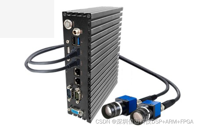
The vision controller is an x86-class embedded PC, which means it runs a full desktop operating system and can host ADTvision natively without a separate host PC. The light source controller sits alongside it in the same enclosure or panel, providing precisely timed illumination that is synchronized with the camera trigger—a necessity for repeatable exposure in factory environments where ambient light varies.
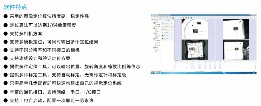
ADTvision Software
ADTvision is Sienovo's proprietary upper-computer (上位机) vision software. Its design goal is minimal configuration overhead: operators set a small number of parameters—camera selection, field of view, coordinate offset, and communication target—and the system is ready to output positioning data. There is no requirement to write custom vision scripts for a standard positioning task.
ADTvision supports both online inspection (live camera feed, real-time result output) and offline inspection (replaying saved images for algorithm tuning or quality audits without tying up production equipment). The offline mode is particularly useful during initial commissioning or when diagnosing intermittent failures.
Camera and Imaging Support
The controller accepts cameras over Gigabit Ethernet (GigE) and USB interfaces, covering the two most common camera buses in modern industrial deployments. GigE Vision cameras offer cable runs up to 100 m without a repeater and are well-suited to fixed machine cells; USB3 Vision cameras provide higher bandwidth for larger sensors at shorter cable distances.
The system specifically supports area scan CCD cameras—the standard choice for precision positioning because CCD sensors deliver uniform sensitivity and low spatial noise across the full frame. Area scan imaging captures a complete 2-D snapshot per trigger, making it ideal for part-present detection, fiducial alignment, and pick-and-place coordinate generation.
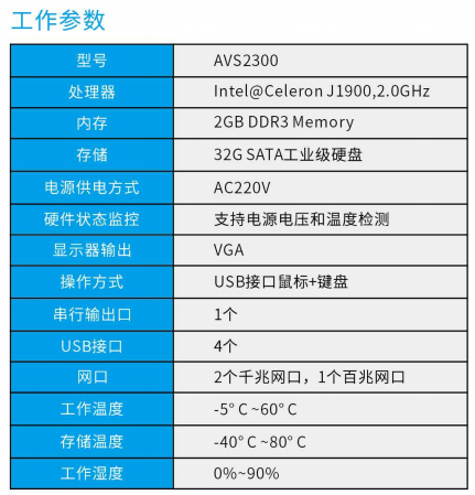
I/O and Communication Interfaces
Connecting vision results back to the line controller is often where projects stall. The AVS system addresses this with a layered communication strategy:
Discrete I/O
- 1× opto-isolated input — typically used to receive the trigger signal from a PLC or motion controller
- 1× opto-isolated output — used to signal pass/fail or "result ready" back to the line
- 2× GPIO — available for auxiliary functions such as lighting enable or encoder input
Opto-isolation on the trigger and result lines is important in panel environments where ground loops and transient noise from servo drives can corrupt logic-level signals.
Serial and fieldbus
- RS232 — simple point-to-point ASCII or binary result transmission to legacy controllers
- Ethernet — both for camera transport (GigE) and for result reporting via TCP/IP sockets or higher-level protocols
Modbus Modbus TCP or Modbus RTU allows the vision controller to appear as a register-mapped device on the factory network. A PLC reads positioning coordinates directly from holding registers, which eliminates custom parsing on the PLC side and works with virtually every modern industrial controller brand.
OPC compliance The system complies with OPC standards, enabling integration with SCADA systems, MES platforms, and data historians that use OPC DA or OPC UA clients. This is the preferred path when positioning data needs to feed into a broader manufacturing intelligence layer.
Light Source Controller Integration
The light source controller is a first-class component in the AVS BOM rather than an afterthought. In precision positioning applications, inconsistent illumination is one of the most common causes of coordinate drift between shifts. By controlling strobe timing and intensity through the same system that drives the camera trigger, the AVS platform keeps imaging conditions repeatable across temperature changes and production runs.
Deployment Scenarios
The combination of high-speed communication options and flexible camera support makes the AVS system applicable across a range of industrial use cases:
- Robot guidance — a robot controller sends a trigger over I/O or Ethernet, receives X/Y/θ coordinates from ADTvision via Modbus, and adjusts its pick path accordingly.
- PCB assembly alignment — fiducial marks are located frame-by-frame; offset corrections are streamed to a motion controller over RS232 or Ethernet.
- Inline quality inspection — the offline inspection mode allows engineering teams to review flagged frames without interrupting production, then update detection parameters and push them back to the live system.
Customization
Sienovo offers customized vision controller configurations to match specific line requirements—different camera interface counts, extended I/O, ruggedized enclosures, or integration with customer-specific communication protocols. Inquiries for custom builds can be directed to Sienovo's industrial solutions team.