Nvidia AGX Xavier GMSL Autonomous Driving Controller Design Solution
Designing an autonomous driving perception controller around NVIDIA Jetson AGX Xavier and GMSL camera serialization involves hardware selection, carrier board layout, and a non-trivial software bring-up sequence. This article walks through Sienovo's GEAC91V platform — a dual-Xavier controller purpose-built for vehicle-grade deployments — and documents the key hardware design decisions and software debugging pitfalls engineers encounter when integrating MAX9296/MAX9295 GMSL2 camera links on Xavier.
Why AGX Xavier for Autonomous Driving?
Environmental perception is the foundation of any autonomous driving stack, and neural network inference is the computational heart of that perception. Traditional general-purpose CPUs cannot sustain the throughput required for real-time multi-camera image processing, LiDAR point cloud fusion, and object detection at automotive frame rates. This gap drove the development of dedicated inference accelerators.
NVIDIA began addressing the automotive segment in 2015 with its DRIVE series of chips and computing platforms. NVIDIA DRIVE™ solutions deliver industry-leading inference performance and come with a mature software stack (DriveWorks, TensorRT, CUDA). However, the DRIVE platform's price point has historically been a barrier for manufacturers of low-speed autonomous vehicles — delivery robots, autonomous forklifts, unmanned boats, and similar platforms — where full DRIVE hardware is over-specified and over-priced.
Jetson AGX Xavier fills that gap. At up to 32 TOPS of combined CPU, GPU, and deep-learning accelerator throughput, Xavier is powerful enough for multi-sensor fusion workloads while remaining accessible to industrial and robotics manufacturers.
GEAC91V: Sienovo's Dual-Xavier Autonomous Driving Controller
To meet strong market demand for an affordable yet vehicle-grade compute platform, Sienovo developed the GEAC91V — a multi-processor controller built on NVIDIA Jetson AGX Xavier modules and targeted at automotive deployments.
Key Architecture
The GEAC91V integrates:
- Dual Jetson AGX Xavier modules operating in Root–Endpoint mode, allowing the two SoCs to share PCIe bandwidth for high-throughput inter-processor communication
- Automotive-grade MCU running a safety-certified RTOS to handle real-time vehicle control tasks that must remain deterministic regardless of the Xavier workload
- CPLD for board-level sequencing, power management arbitration, and glue logic
- Hardware timing and synchronization circuit — an onboard PPS/GPRMC time source provides a reliable clock reference for sensor fusion across all attached cameras, LiDAR, and IMU devices
Interface Summary
| Interface | Count / Spec |
|---|---|
| GMSL2 camera inputs | 12 lanes, each independently triggerable |
| CAN bus | 12 channels |
| LIN bus | 2 channels |
| Gigabit automotive Ethernet | 2 ports |
| 10 Gigabit Ethernet | 1 port |
| LiDAR encoder signal input | Supported |
| Time sync outputs | PPS, GPRMC, Trigger, PTP |
| Power input | Dual redundant supply |
All primary connectors are automotive-grade or M12 industrial-grade. The enclosure carries an IP67 rating, operates from −20 °C to +60 °C, survives 36 ms⁻¹ / 1000 Hz random vibration, and is rated for an MTBF of 50,000 hours. The design meets CE-EMC certification requirements.
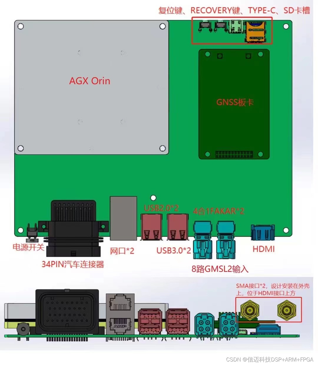
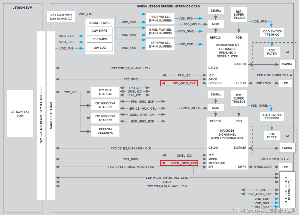
Hardware Design for GMSL2 on Jetson AGX Xavier
The hardware bring-up targets the standard Jetson AGX Xavier DevKit 120-pin connector (Samtec QSH-060-01-H-D-A-K-TR). The full design goals are:
- Support Jetson Xavier AGX Devkit 120-pin connector (QSH-060-01-H-D-A-K-TR, Samtec)
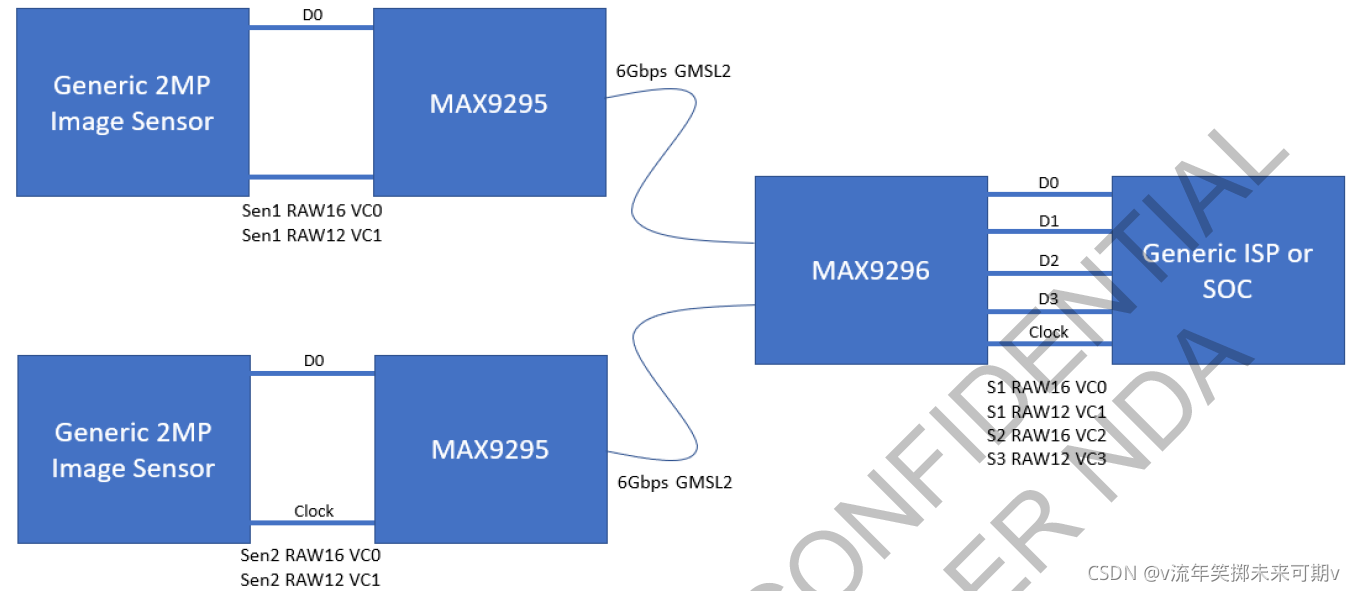
- GMSL Deserializer: MAX9296
- Support multiple MAX9295 serializer cameras
- Backward-compatible with MAX96705 (GMSL1)
- Support Virtual Channel operation
- Support Frame Sync and independent per-lane Trigger
Design Decisions Worth Noting
Deserializer selection — MAX9296 at 6 Gbps. The MAX9296 supports 6 Gbps link rates versus the 3 Gbps of GMSL1 deserializers. This higher bandwidth supports higher-resolution sensors and faster frame rates without link saturation, which matters for 8 MP surround-view camera arrays.
POC (Power-over-Coax) backward compatibility with GMSL1. Maxim's default MAX9296 reference design does not enable GMSL1 backward compatibility out of the box. The carrier board's POC section requires additional design work — specifically in the bias and termination network on the coax side — to allow GMSL1 cameras (e.g., MAX96705-based modules) to link up alongside GMSL2 cameras.
8-camera synchronous trigger. Achieving frame-synchronized capture across 8 independent camera streams requires routing a common trigger signal to each MAX9295 serializer's MFP (Multi-Function Pin) GPIO. The trigger can originate from the Xavier itself or from the onboard hardware timing circuit. Each lane on the GEAC91V supports independent triggering, giving the system flexibility to synchronize subsets of cameras with different exposure requirements.
GMSL + LiDAR time synchronization. Fusing camera frames with LiDAR point clouds requires both sensor types to share a common time base. The GEAC91V's hardware PPS circuit provides a sub-microsecond timing reference distributed to all sensors simultaneously via PPS, GPRMC, and PTP interfaces.
I²C topology and expander selection. Each MAX9296 deserializer exposes an I²C master port through which the host can reach downstream MAX9295 serializers and camera sensors. With 12 GMSL lanes, the I²C address space and bus loading must be managed carefully. I²C expander IC selection and address translation configuration are non-trivial; budget time for this during schematic review.
Passive component selection — inductors in particular. In POC and power supply filtering sections, inductor selection affects both EMI compliance and link signal integrity. Using inductors with insufficient current rating or excessive DCR can cause marginal link behavior that is difficult to debug. Use the values and part types from Maxim's reference design as a starting point.
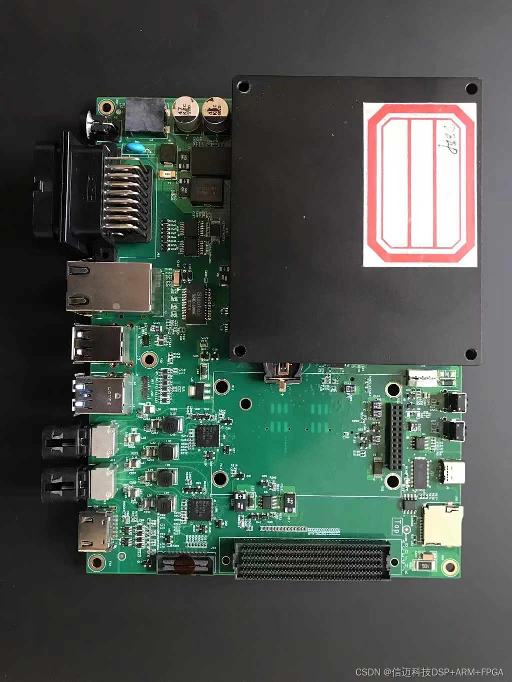
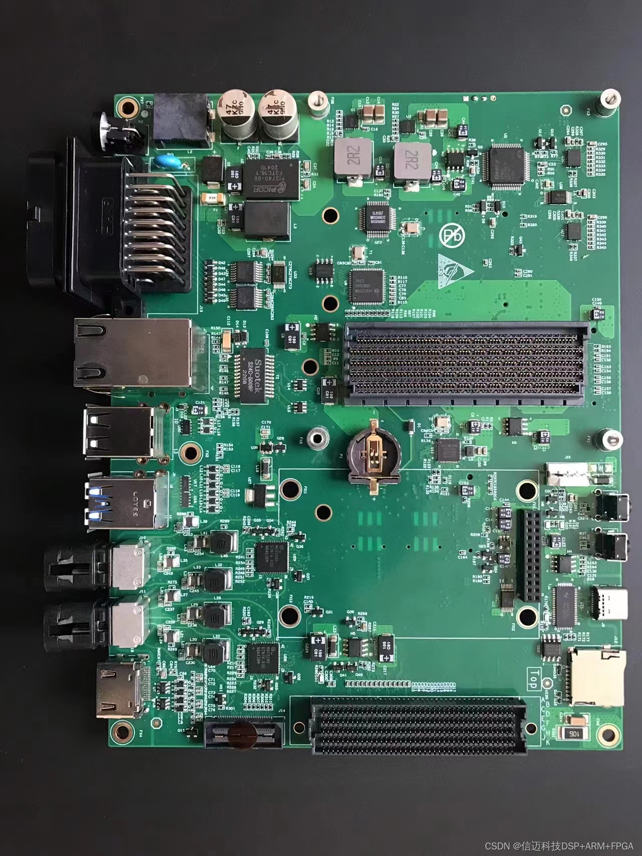
Hardware block diagrams:
Software Bring-Up: Debugging Pitfalls
GMSL camera bring-up on Xavier has a reliable step-by-step sequence. Skipping steps or jumping straight to video capture is a common mistake that makes root-cause analysis very hard. The recommended sequence, with the pitfalls Sienovo's team recorded:
Step 1 — Verify MAX9296 I²C without any camera attached.
Before connecting any GMSL camera, confirm that the host can read and write MAX9296 registers over I²C.
Problem encountered: I²C not responding. Checklist: verify MAX9296 power rail is up, check PWDN pin polarity and state, confirm the crystal oscillator is running, verify I²C address selection resistors match your driver configuration.
Step 2 — Attach a MAX9295 camera and verify serializer I²C.
Once the deserializer is confirmed healthy, connect one camera and attempt to read MAX9295 registers (reached through the MAX9296 I²C master port).
Problem encountered: I²C still not responding through the link. Checklist: confirm 12 V camera supply is present and within spec, verify MAX9296 initialization completed successfully before attempting to access the serializer (the link must be locked first), confirm POC current limit is not tripping.
Step 3 — Confirm /dev/video* device nodes are created.
On a correctly configured JetPack kernel with the appropriate device tree overlay, the V4L2 device nodes should appear once the deserializer driver initializes. If they are absent, the driver either failed to probe or the device tree binding is incorrect.
Step 4 — Check pipeline lock and video link status registers.
Read the MAX9296 pipeline lock register and the video link detect/lock status bits. A locked link is a prerequisite for any valid video. If the pipeline is not locked, no amount of software configuration will produce frames.
Step 5 — Open the camera with the correct format command.
The correct v4l2-ctl or GStreamer command depends on the sensor output format:
- RAW Bayer sensors require a different media-pipeline configuration than YUV sensors
- Confirm
media-ctlformat strings match the sensor's actual output format and resolution
Step 6 — Verify MFP GPIO configuration for synchronization.
Each MAX9295 serializer exposes Multi-Function Pins that can be configured as frame sync inputs or trigger outputs. Confirm the MFP assigned to frame sync is configured correctly in both the deserializer and serializer register maps.
Step 7 — Debug trigger synchronization with a scope.
If synchronization is unstable or absent, use an oscilloscope to probe the MFP signal pins on the serializer side. If the waveform is absent or malformed, the MFP register configuration has not taken effect — re-check the initialization sequence and register write order.
Summary and Takeaways
-
GMSL has meaningful advantages over FPD-Link in terms of link stability, ecosystem breadth, price, and supply availability. For new autonomous driving and industrial vision designs, GMSL2 is the stronger default choice.
-
Competition is broadening the GMSL SerDes market. Beyond Maxim (now part of Analog Devices), Japanese manufacturer ROHM has entered the GMSL SerDes space with mature chips already in commercial deployment. This improves supply security and pricing leverage.
-
GMSL serializer/deserializer design and bring-up require accumulated experience. The interaction between POC design, I²C topology, link initialization sequence, and kernel driver configuration creates many subtle failure modes. Teams new to GMSL should budget significant debug time for their first design. Following a strict step-by-step bring-up sequence — power → I²C → link lock → device nodes → format → sync — prevents conflating symptoms from unrelated root causes.